
Brochures and Data Sheets

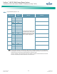


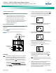
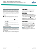
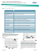
Table Of Contents
- Admonishments Used In This Document
- Important Safety Instructions
- Static Warning
- System Overview
- Installation Acceptance Checklist
- Installing the System
- General Requirements
- Securing the Relay Rack to the Floor
- Mounting System Components in a Relay Rack
- Setting Switch Options
- Making Electrical Connections
- Important Safety Instructions
- Wiring Considerations
- Relay Rack Grounding Connection (Frame Ground)
- AC Input and AC Input Equipment Grounding Connections to Rectifier Module Mounting Shelves
- External Alarm, Reference, Monitoring, and Control Connections
- ACU+ Controller Ethernet Connection (if required)
- -48V DC Output Connections
- Installing the Rectifier Modules and Initially Starting the System
- Installing the Rectifier Modules into Spec. No. 588705000 Rectifier Module Mounting Shelves
- Initially Starting, Configuring, and Checking System Operation
- Important Safety Instructions
- Initial Startup Preparation
- Initially Starting the System
- ACU+ Controller Initialization
- Verifying the Configuration File
- Checking Basic System Settings
- Changing Battery Capacity Rating in the ACU+
- Configuring the ACU+ Identification of Rectifiers and Assigning which Input Phase is Connected to the Rectifiers
- ACU+ Alarm Relay Check
- Checking System Status
- Final Steps
- Operating Procedures
- Maintenance
- Troubleshooting and Repair
- NetPerform™ Optimization Services
NetSure
™
-48V DC Bulk Output Power System
Installation and User Instructions, UM582127100 (Issue AA, May 7, 2013)
Spec. No: 582127100 UM582127100
Model No: 722NBBB Issue AA, May 7, 2013
25
ACU+ Controller CAN Bus
The end of the ACU+ CAN Bus is routed into the ACU+ section of
the main rectifier module mounting shelf via cable P/N 556430.
Use cable P/N 556238 to connect external devices to the end of
the ACU+ CAN bus. Access the ACU+ CAN Bus connector by
removing the top cover from the ACU+ section of the main
rectifier module mounting shelf. A CAN termination plug must be
installed if an external device or system is not connected here.
Refer to Figure 5, Figure 12, and Table 5.
Table 5. ACU+ Controller CAN Bus Cables
P/N 556430 (Int. CAN) Cable
Signal
Wire Color
Pinouts
CAN-H
Black
CANx-1
CAN-L
Red
CANx-2
P/N 556238 (Ext. CAN) Cable
Signal
Wire Color
Pinouts
CAN-H
Black
CANx-1
CAN-L
Red
CANx-2
Connecting a Device or System to the ACU+ CAN Bus
A supporting device or system may be connected to the ACU+ CAN
Port. Refer to Figure 5 and Figure 12 for location. A 10’ long ACU+
CAN Bus Cable is available (P/N 556238) to extend the end of the
ACU+ CAN Bus outside the main rectifier module mounting shelf
to other equipment. See Table 5 for cable pinouts and wire colors.
Refer also to the external device’s or system’s instruction manual.
PROCEDURE
1. Remove the CAN termination plug from the ACU+ CAN
Port (see Figure 5 and Figure 12 for location). Connect
the device or system to the ACU+ CAN Port using cable
P/N 556238. Refer to Table 5 for cable pinouts and wire
colors. Note that you may have to cut the end off of the
cable if it is not compatible with the device’s CAN Bus
connection points. Refer also to the external device’s or
system’s instruction manual.
Optional SM-Temp Module
The analog output of the SM-Temp Module may be connected to
an ACU+ temperature port input. In lieu of connecting the analog
output of the SM-TEMP module to an ACU+ temperature port
input, the SM-TEMP module can simply be connected at the end of
the ACU+ CAN Bus (requires ACU+ version 3.02 or later). Refer to
the SM-Temp Module Instructions (UM547490) for details.
PROCEDURE
1. Remove the CAN termination plug from the ACU+ CAN
Port (see Figure 5 and Figure 12 for location). Connect
the SM-Temp Module CAN Bus to the ACU+ CAN Port
using cable P/N 556238. Refer to Table 2 for cable
pinouts and wire colors. Note that you will have to cut
the end off of the cable to connect it to the SM-Temp
Module’s CAN Bus connection points. Ensure the last SM-
Temp Module (or if only one) has a CAN termination strap
as shown in the SM-Temp Module Instructions
(UM547490).
ACU+ Controller Ethernet Connection (if required)
The ACU+ Controller provides a Web Interface via an Ethernet
connection to a TCP/IP network. This interface can be accessed
locally on a computer or remotely through a network. An RJ-45
10BaseT jack is provided on the front of the ACU+ for connection
into a customer's network. This jack has a standard Ethernet pin
configuration scheme, twisted pair. Refer to Figure 11 for location
and Table 6 for pin outs. Use shielded Ethernet cable (grounded at
both ends). Note that the ACU+ RJ-45 jack is connected to chassis
ground. Refer to the ACU+ Instructions (UM1M820BNA) for
operational details.
Note: You can access the Web pages of the power system locally by
using a "crossover" or “straight” cable connected directly
between your PC and the ACU+.
Warning! The intra-building port(s) of the equipment or
subassembly is suitable for connection to intra-building
or unexposed wiring or cabling only. The intra-building
port(s) of the equipment or subassembly MUST NOT be
metallically connected to the interfaces that connect to
the OSP or its wiring. These interfaces are designed for
use as intra-building interfaces only (Type 2 or Type 4
ports as described in GR-1089-CORE, Issue 4) and
require isolation from the exposed OSP cabling. The
addition of Primary Protectors is not sufficient
protection in order to connect these interfaces
metallically to OSP wiring.
The intra-building port (RJ-45) of the equipment or
subassembly must use shielded intra-building
cabling/wiring that is grounded at both ends.