
Brochures and Data Sheets

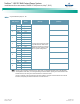


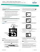
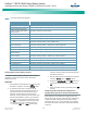
Table Of Contents
- Admonishments Used In This Document
- Important Safety Instructions
- Static Warning
- System Overview
- Installation Acceptance Checklist
- Installing the System
- General Requirements
- Securing the Relay Rack to the Floor
- Mounting System Components in a Relay Rack
- Setting Switch Options
- Making Electrical Connections
- Important Safety Instructions
- Wiring Considerations
- Relay Rack Grounding Connection (Frame Ground)
- AC Input and AC Input Equipment Grounding Connections to Rectifier Module Mounting Shelves
- External Alarm, Reference, Monitoring, and Control Connections
- ACU+ Controller Ethernet Connection (if required)
- -48V DC Output Connections
- Installing the Rectifier Modules and Initially Starting the System
- Installing the Rectifier Modules into Spec. No. 588705000 Rectifier Module Mounting Shelves
- Initially Starting, Configuring, and Checking System Operation
- Important Safety Instructions
- Initial Startup Preparation
- Initially Starting the System
- ACU+ Controller Initialization
- Verifying the Configuration File
- Checking Basic System Settings
- Changing Battery Capacity Rating in the ACU+
- Configuring the ACU+ Identification of Rectifiers and Assigning which Input Phase is Connected to the Rectifiers
- ACU+ Alarm Relay Check
- Checking System Status
- Final Steps
- Operating Procedures
- Maintenance
- Troubleshooting and Repair
- NetPerform™ Optimization Services
NetSure
™
-48V DC Bulk Output Power System
Installation and User Instructions, UM582127100 (Issue AA, May 7, 2013)
Spec. No: 582127100 UM582127100
Model No: 722NBBB Issue AA, May 7, 2013
24
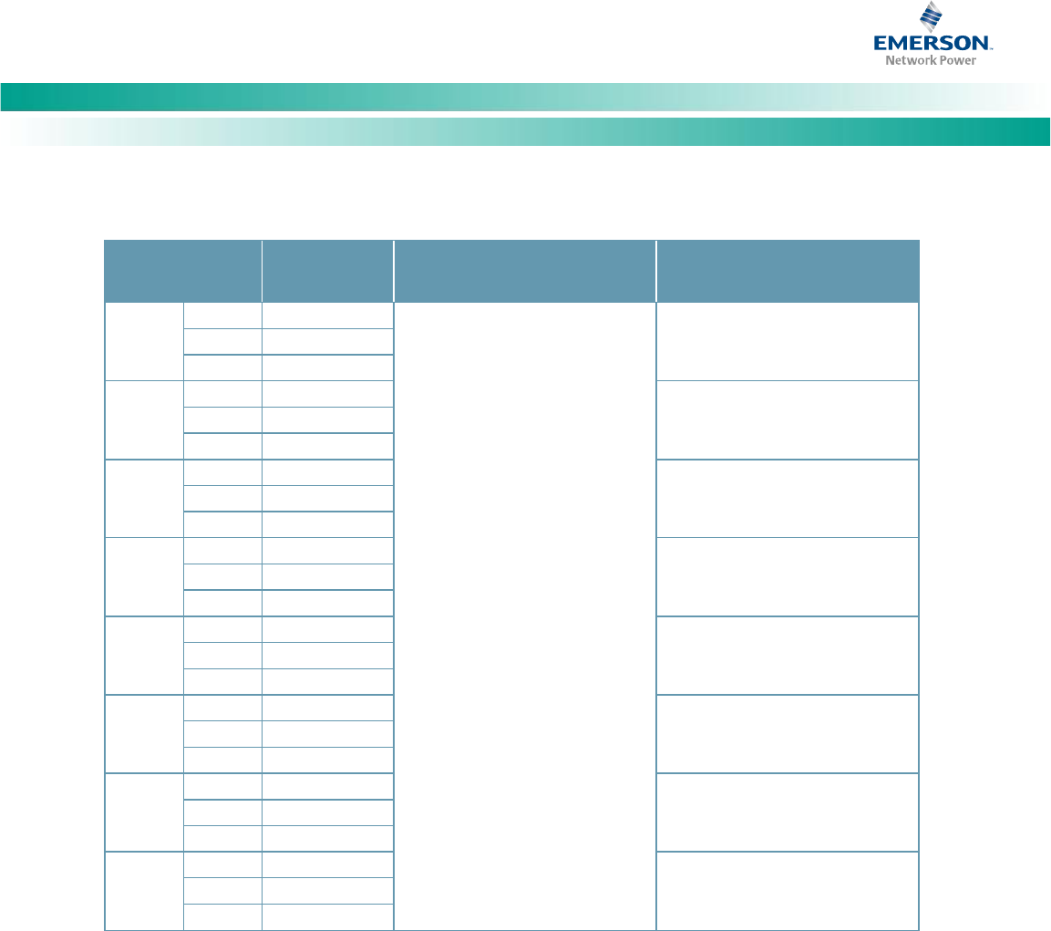
Table 4. Programmable Relay Outputs – IB2
Programmable
Relay Output
IB2
Pin No.
Alarms Assigned to this Relay
(Default)
Alarms Assigned to this Relay
(Custom)
1
NO
J6-5
The relays may be preprogrammed
for specific functions. Refer to the
configuration drawing (C-drawing)
supplied with your system for your
system’s specific configuration.
COM
J6-3
NC
J6-1
2
NO
J6-6
COM
J6-4
NC
J6-2
3
NO
J7-5
COM
J7-3
NC
J7-1
4
NO
J7-6
COM
J7-4
NC
J7-2
5
NO
J8-5
COM
J8-3
NC
J8-1
6
NO
J8-6
COM
J8-4
NC
J8-2
7
NO
J9-5
COM
J9-3
NC
J9-1
8
NO
J9-6
COM
J9-4
NC
J9-2
Note: The ACU+ relay assigned to “Critical Summary” alarm (relay 1 by default) will operate in the “Fail Safe Mode”.
“Fail Safe Mode” means Relay 1 is de-energized during an alarm condition, opening the contacts between the C
and NO terminals, and closing the contacts between the C and NC terminals.
The ACU+ remaining 7 relays energize during an alarm condition, closing the contacts between the C and NO
terminals, and opening the contacts between the C and NC terminals.