
Brochures and Data Sheets

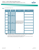


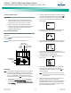
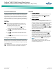
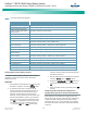
Table Of Contents
- Admonishments Used In This Document
- Important Safety Instructions
- Static Warning
- System Overview
- Installation Acceptance Checklist
- Installing the System
- General Requirements
- Securing the Relay Rack to the Floor
- Mounting System Components in a Relay Rack
- Setting Switch Options
- Making Electrical Connections
- Important Safety Instructions
- Wiring Considerations
- Relay Rack Grounding Connection (Frame Ground)
- AC Input and AC Input Equipment Grounding Connections to Rectifier Module Mounting Shelves
- External Alarm, Reference, Monitoring, and Control Connections
- ACU+ Controller Ethernet Connection (if required)
- -48V DC Output Connections
- Installing the Rectifier Modules and Initially Starting the System
- Installing the Rectifier Modules into Spec. No. 588705000 Rectifier Module Mounting Shelves
- Initially Starting, Configuring, and Checking System Operation
- Important Safety Instructions
- Initial Startup Preparation
- Initially Starting the System
- ACU+ Controller Initialization
- Verifying the Configuration File
- Checking Basic System Settings
- Changing Battery Capacity Rating in the ACU+
- Configuring the ACU+ Identification of Rectifiers and Assigning which Input Phase is Connected to the Rectifiers
- ACU+ Alarm Relay Check
- Checking System Status
- Final Steps
- Operating Procedures
- Maintenance
- Troubleshooting and Repair
- NetPerform™ Optimization Services
NetSure
™
-48V DC Bulk Output Power System
Installation and User Instructions, UM582127100 (Issue AA, May 7, 2013)
Spec. No: 582127100 UM582127100
Model No: 722NBBB Issue AA, May 7, 2013
23
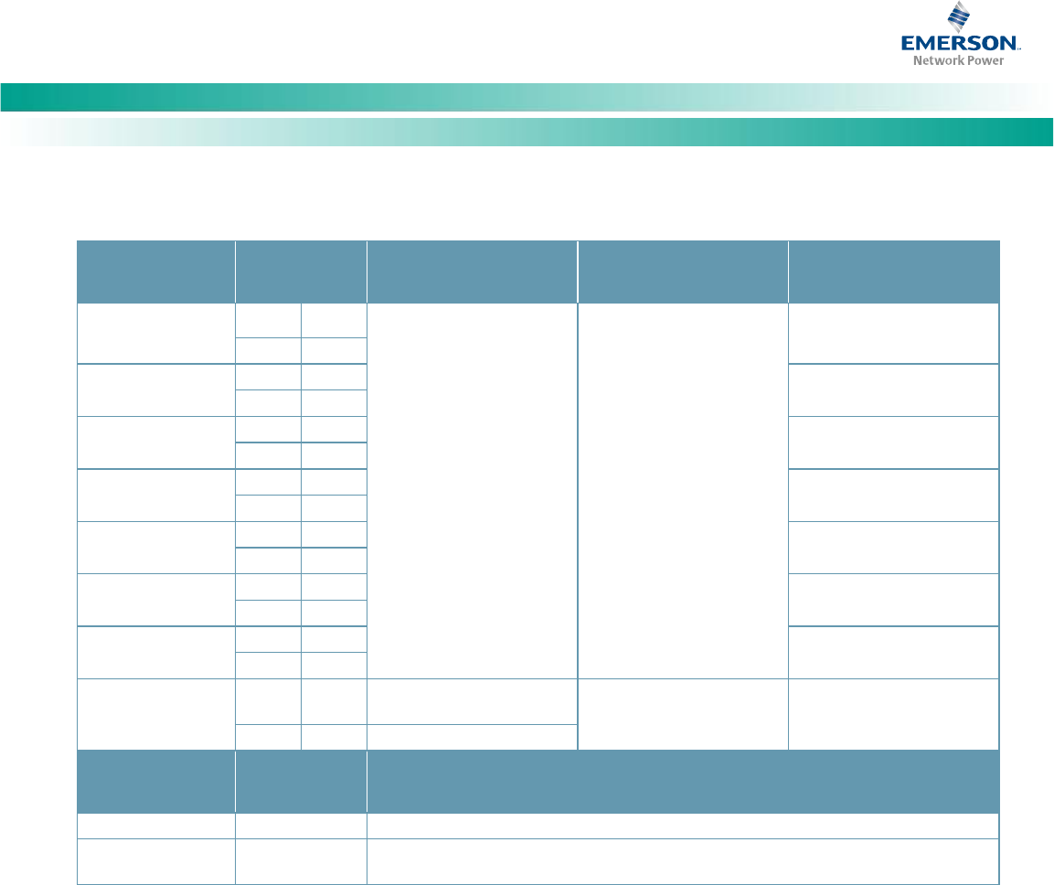
Table 3. Programmable Digital Inputs – IB2
Programmable
Digital Input
IB2
Pin No.
Factory
Wiring
Default Digital
Input Function
Customer Defined
Digital Input Function
1
J3-2
+
The digital inputs may be
preprogrammed for specific
functions and have factory
wiring connected. Refer to
the configuration drawing
(C-drawing) supplied with
your system for your
system’s specific
configuration.
The digital inputs may be
preprogrammed for specific
functions. Refer to the
configuration drawing (C-
drawing) supplied with your
system for your system’s
specific configuration.
J3-1
–
2
J3-4
+
J3-3
–
3
J3-6
+
J3-5
–
4
J4-2
+
J4-1
–
5
J4-4
+
J4-3
–
6
J4-6
+
J4-5
–
7
J5-2
+
J5-1
–
8
J5-4
+
(to customer
ESTOP switch)
ESTOP
J5-3
–
to J5-6 (-48VDC)
Reference
Voltages
IB2
Pin No.
Factory Wiring
Ground
J5-5
(can be connected to the other side of a customer furnished ESTOP switch)
-48VDC
J5-6
-48VDC is factory supplied to J5-6.
J5-6 is also factory jumpered to J5-3 (Digital Input #8, minus)
Note: -48VDC is factory supplied to J5-6 which is also factory jumpered to J5-3 (Digital Input #8, minus). A customer provided ESTOP
switch can be connected to J5-4 (Digital Input #8, positive). Note that ground is furnished on J5-5 for a convenient connection to
the other side of a customer provided ESTOP switch. Digital Input #8 is factory configured for the ESTOP function. Customer-
furnished system ground applied to terminal J5-4 (Digital Input #8, positive) activates the ESTOP function. The ESTOP function
shuts down and locks out the rectifiers and opens the LVD’s. When the ESTOP signal is removed, LVD’s close (if battery present).
To restart the rectifiers; turn AC power to the rectifiers OFF, wait 30 seconds or more (until the LEDs on the rectifier extinguish),
then turn AC power to the rectifiers ON. Rectifiers can also be restarted from the ACU+ LCD or WEB Interface menu (via the
Rectifier Reset command, found in the Manual menu in the LCD menus or under the Rectifier Control Tab in the WEB Interface).