
Brochures and Data Sheets
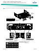
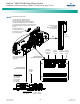
Table Of Contents
- Admonishments Used In This Document
- Important Safety Instructions
- Static Warning
- System Overview
- Installation Acceptance Checklist
- Installing the System
- General Requirements
- Securing the Relay Rack to the Floor
- Mounting System Components in a Relay Rack
- Setting Switch Options
- Making Electrical Connections
- Important Safety Instructions
- Wiring Considerations
- Relay Rack Grounding Connection (Frame Ground)
- AC Input and AC Input Equipment Grounding Connections to Rectifier Module Mounting Shelves
- External Alarm, Reference, Monitoring, and Control Connections
- ACU+ Controller Ethernet Connection (if required)
- -48V DC Output Connections
- Installing the Rectifier Modules and Initially Starting the System
- Installing the Rectifier Modules into Spec. No. 588705000 Rectifier Module Mounting Shelves
- Initially Starting, Configuring, and Checking System Operation
- Important Safety Instructions
- Initial Startup Preparation
- Initially Starting the System
- ACU+ Controller Initialization
- Verifying the Configuration File
- Checking Basic System Settings
- Changing Battery Capacity Rating in the ACU+
- Configuring the ACU+ Identification of Rectifiers and Assigning which Input Phase is Connected to the Rectifiers
- ACU+ Alarm Relay Check
- Checking System Status
- Final Steps
- Operating Procedures
- Maintenance
- Troubleshooting and Repair
- NetPerform™ Optimization Services
NetSure
™
-48V DC Bulk Output Power System
Installation and User Instructions, UM582127100 (Issue AA, May 7, 2013)
Spec. No: 582127100 UM582127100
Model No: 722NBBB Issue AA, May 7, 2013
22
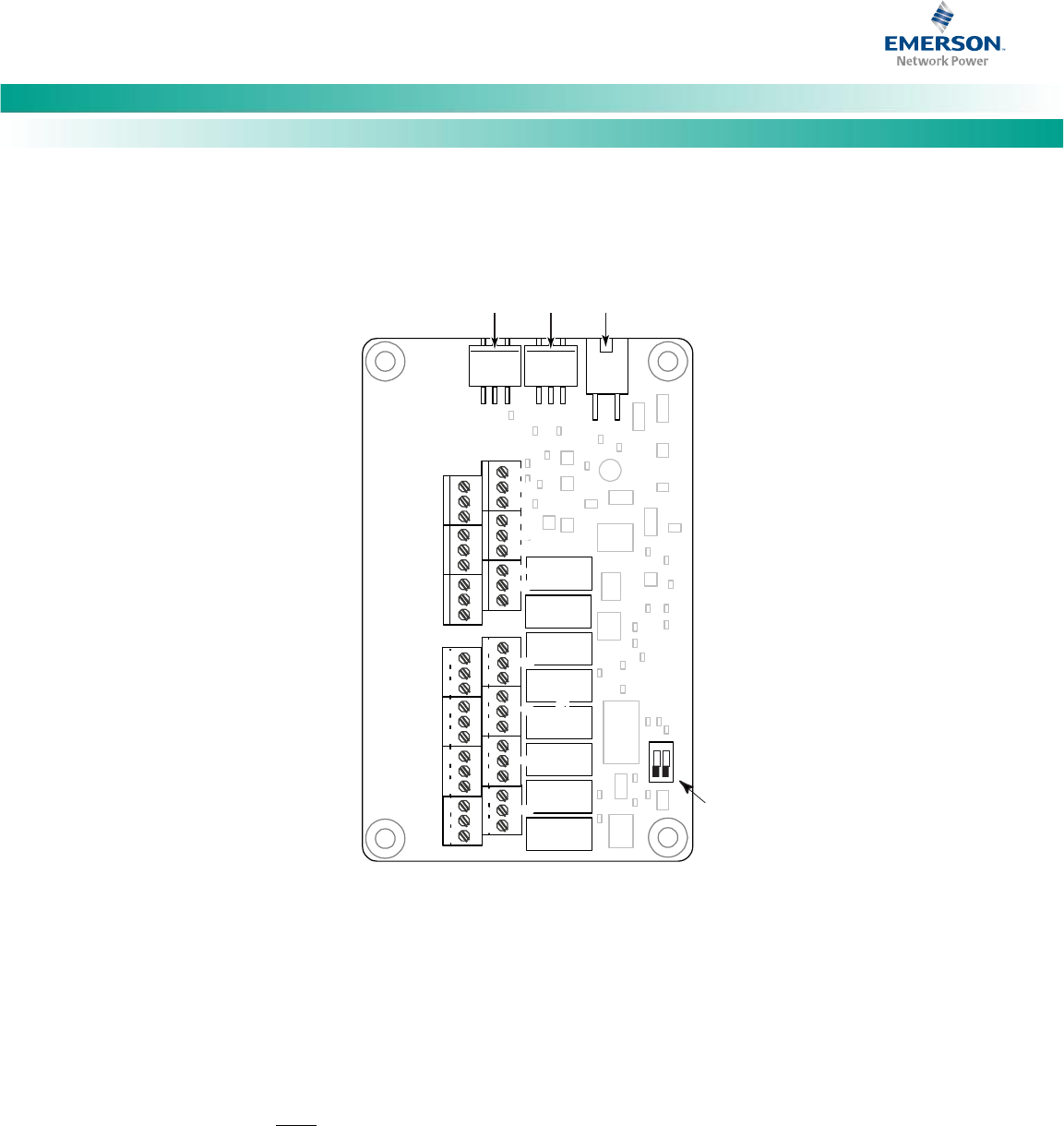
Figure 13. IB2 (Interface Board) Connections
IB2
(ACU+ Interface Board)
Switch settings must be in this position
to interface with the ACU+ Controller
-
J12
*
RELAY
SW1
7
J2
J11
5 3
1
Relay Output Terminal Blocks
Digital Input Terminal Blocks
J9 J8 J7
J6
J5 J4 J3
8 6 4
2
8 7 6 5 4 3
2 1
+
IB2 Board (Top View)
NO
C
NC
NO C NC
NO
C
NC
NO C NC
NO
C
NC
NO C NC
NO
C
NC
NO C NC
5
3
1
46 2
5 3 1
46 2
5
3
1
46 2
5 3 1
46 2
5
3
1
46 2
5
3
1
46 2
5 3 1
46 2
Connector
to ACU+
IB2 TEMP
PROBRE 1
IB2 TEMP
PROBE 2
* The ACU+ relay assigned to “Critical Summary” alarm (relay 1 by default)
will operate in the “Fail Safe Mode”. “Fail Safe Mode” means Relay 1 is
de-energized during an alarm condition, opening the contacts between the
C and NO terminals, and closing the contacts between the C and NC terminals.
The ACU+’s remaining seven (7) relays energize during an alarm condition, closing
the contacts between the C and NO terminals, and opening the contacts between
the C and NC terminals.
Not all I/O points are available for customer connection (some are used for factory
system connections).
J3-J9:
Wire Size Capacity: 16-26 AWG.
Recommended Torque: 2.2 in-lbs.