
Brochures and Data Sheets
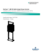

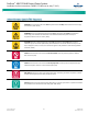

Table Of Contents
- Admonishments Used In This Document
- Important Safety Instructions
- Static Warning
- System Overview
- Installation Acceptance Checklist
- Installing the System
- General Requirements
- Securing the Relay Rack to the Floor
- Mounting System Components in a Relay Rack
- Setting Switch Options
- Making Electrical Connections
- Important Safety Instructions
- Wiring Considerations
- Relay Rack Grounding Connection (Frame Ground)
- AC Input and AC Input Equipment Grounding Connections to Rectifier Module Mounting Shelves
- External Alarm, Reference, Monitoring, and Control Connections
- ACU+ Controller Ethernet Connection (if required)
- -48V DC Output Connections
- Installing the Rectifier Modules and Initially Starting the System
- Installing the Rectifier Modules into Spec. No. 588705000 Rectifier Module Mounting Shelves
- Initially Starting, Configuring, and Checking System Operation
- Important Safety Instructions
- Initial Startup Preparation
- Initially Starting the System
- ACU+ Controller Initialization
- Verifying the Configuration File
- Checking Basic System Settings
- Changing Battery Capacity Rating in the ACU+
- Configuring the ACU+ Identification of Rectifiers and Assigning which Input Phase is Connected to the Rectifiers
- ACU+ Alarm Relay Check
- Checking System Status
- Final Steps
- Operating Procedures
- Maintenance
- Troubleshooting and Repair
- NetPerform™ Optimization Services

NetSure
™
-48V DC Bulk Output Power System
Installation and User Instructions, UM582127100 (Issue AA, May 7, 2013)
Spec. No: 582127100 UM582127100
Model No: 722NBBB Issue AA, May 7, 2013
i
Table of Contents
Admonishments Used In This Document............................................................................................................... iii
Important Safety Instructions .............................................................................................................................. iv
General Safety ........................................................................................................................................................iv
Voltages .................................................................................................................................................................iv
Battery ...................................................................................................................................................................iv
Circuit Card Handling ..............................................................................................................................................iv
Static Warning ...................................................................................................................................................... v
System Overview .................................................................................................................................................. 1
Customer Documentation Package ......................................................................................................................... 1
System Description ................................................................................................................................................. 1
Installation Acceptance Checklist .......................................................................................................................... 1
Installing the System ............................................................................................................................................. 2
General Requirements ............................................................................................................................................ 2
Securing the Relay Rack to the Floor ........................................................................................................................ 2
Mounting System Components in a Relay Rack ........................................................................................................ 2
Setting Switch Options ........................................................................................................................................ 10
Switch Settings on IB2 Interface Board .................................................................................................................. 10
Making Electrical Connections ............................................................................................................................ 11
Important Safety Instructions................................................................................................................................ 11
Wiring Considerations .......................................................................................................................................... 11
Relay Rack Grounding Connection (Frame Ground) ............................................................................................... 11
AC Input and AC Input Equipment Grounding Connections to Rectifier Module Mounting Shelves .......................... 12
External Alarm, Reference, Monitoring, and Control Connections .......................................................................... 17
ACU+ Controller Ethernet Connection (if required) ................................................................................................ 25
-48V DC Output Connections ................................................................................................................................ 26
Installing the Rectifier Modules and Initially Starting the System ......................................................................... 29
Installing the Rectifier Modules into Spec. No. 588705000 Rectifier Module Mounting Shelves ............................... 29
Initially Starting, Configuring, and Checking System Operation.............................................................................. 29
Operating Procedures ......................................................................................................................................... 35
Controller and Rectifiers ....................................................................................................................................... 35
ESTOP Function .................................................................................................................................................... 35
ACU+ Battery Charge Current Limit Feature ........................................................................................................... 35
Local Controls and Indicators ................................................................................................................................ 35
Maintenance ....................................................................................................................................................... 35
System Maintenance Procedures .......................................................................................................................... 35
Adding a Rectifier Module to an Existing Rectifier Module Mounting Shelf Spec. No. 588705000 ............................ 35
Installing a Field Expansion Rectifier Module Mounting Shelf Spec. No. 588705000 ................................................ 35
Troubleshooting and Repair ................................................................................................................................ 36
Contact Information ............................................................................................................................................. 36
Controller and Rectifiers ....................................................................................................................................... 36