
Brochures and Data Sheets
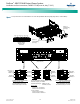
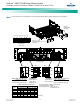
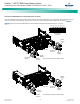
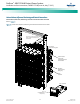
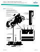
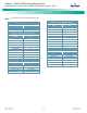
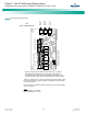
Table Of Contents
- Admonishments Used In This Document
- Important Safety Instructions
- Static Warning
- System Overview
- Installation Acceptance Checklist
- Installing the System
- General Requirements
- Securing the Relay Rack to the Floor
- Mounting System Components in a Relay Rack
- Setting Switch Options
- Making Electrical Connections
- Important Safety Instructions
- Wiring Considerations
- Relay Rack Grounding Connection (Frame Ground)
- AC Input and AC Input Equipment Grounding Connections to Rectifier Module Mounting Shelves
- External Alarm, Reference, Monitoring, and Control Connections
- ACU+ Controller Ethernet Connection (if required)
- -48V DC Output Connections
- Installing the Rectifier Modules and Initially Starting the System
- Installing the Rectifier Modules into Spec. No. 588705000 Rectifier Module Mounting Shelves
- Initially Starting, Configuring, and Checking System Operation
- Important Safety Instructions
- Initial Startup Preparation
- Initially Starting the System
- ACU+ Controller Initialization
- Verifying the Configuration File
- Checking Basic System Settings
- Changing Battery Capacity Rating in the ACU+
- Configuring the ACU+ Identification of Rectifiers and Assigning which Input Phase is Connected to the Rectifiers
- ACU+ Alarm Relay Check
- Checking System Status
- Final Steps
- Operating Procedures
- Maintenance
- Troubleshooting and Repair
- NetPerform™ Optimization Services

NetSure
™
-48V DC Bulk Output Power System
Installation and User Instructions, UM582127100 (Issue AA, May 7, 2013)
Spec. No: 582127100 UM582127100
Model No: 722NBBB Issue AA, May 7, 2013
21
IB2 (ACU+ Interface Board) Connections (if required)
The IB2 (ACU+ Interface Board) provides connection points for
digital inputs, programmable relay outputs, and temperature
probes. The IB2 interface board is mounted inside the main
rectifier module mounting shelf. Refer to Figure 11.
Digital Inputs and Programmable Relay Outputs
Digital input and relay output leads are connected to screw-type
terminal blocks located on the IB2. Recommended torque for
these connections is 2.2 in-lbs. Refer to Figure 13 for terminal
locations. Refer to Table 3 and Table 4 for pin-out information.
Digital Inputs
Connect up to eight (8) digital inputs to the IB2. Note that you
must supply both paths for the digital input (either a positive or
negative signal and the opposite polarity return path). Observe
proper polarity. Refer to Figure 13 for terminal locations and Table
3 for pin-out information.
The digital inputs can be programmed to provide an alarm when
the signal is applied (HIGH) or removed (LOW). Refer to the ACU+
Instructions (UM1M820BNA) for programming information.
Digital Input Ratings: Refer to the following.
a. Maximum Voltage Rating: 60V DC.
b. Active High: > 19V DC.
c. Active Low: < 1V DC.
The digital inputs may be preprogrammed for specific functions.
Refer to the configuration drawing (C-drawing) supplied with your
system for your system’s specific configuration.
Programmable Relay Outputs
The IB2 provides eight (8) programmable alarm relays with dry
Form-C contacts. Connect up to eight (8) relay outputs to the IB2.
Refer to Figure 13 for terminal locations and Table 4 for pin-out
information.
Refer to the ACU+ Instructions (UM1M820BNA) for programming
information.
Relay Ratings: Refer to the following.
a. 1A Steady State @ 30V DC.
b. 3A Peak @ 30V DC.
The relays may be preprogrammed for specific functions. Refer to
the configuration drawing (C-drawing) supplied with your system
for your system’s specific configuration.
Temperature Probes
Note: Each temperature probe consists of two pieces that plug
together to make a complete probe. See SAG582127100 for
part numbers and descriptions.
Temperature probes are connected to the IB2 (ACU+ Interface
Board) and/or the system external interface board mounted inside
the main rectifier module mounting shelf. See Figure 12 and
Figure 13.
Up to two (2) temperature probes can be connected to the IB2. Up
to two (2) additional temperature probes can be connected to the
system external interface board. Any combination of the four (4)
temperature probes can be programmed to monitor ambient
temperature and/or battery temperature. A temperature probe
set to monitor battery temperature can also be used for the
rectifier battery charge temperature compensation feature, or the
battery charge temperature compensation feature can be
programmed to use the average or highest value of all battery
temperature probes. The battery charge temperature
compensation feature allows the controller to automatically
increase or decrease the output voltage of the system to maintain
battery float current as battery temperature decreases or
increases, respectively. Battery life can be extended when an
optimum charge voltage to the battery with respect to
temperature is maintained. A temperature probe set to monitor
battery temperature can also be used for the BTRM (Battery
Thermal Runaway Management) feature. The BTRM feature
lowers output voltage when a high temperature condition exists to
control against battery thermal runaway.
The temperature sensor end of the probe contains a tab with a
5/16” clearance hole for mounting.
A temperature probe programmed to monitor battery
temperature should be mounted on the negative post of a battery
cell to sense battery temperature. A temperature probe used for
battery charge temperature compensation and/or BTRM (Battery
Thermal Runaway Management) should also be mounted on the
negative post of a battery cell. A temperature probe programmed
to monitor ambient temperature should be mounted in a
convenient location, away from direct sources of heat or cold.