
Brochures and Data Sheets
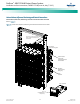
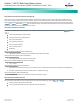
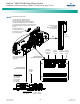
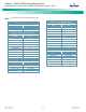
Table Of Contents
- Admonishments Used In This Document
- Important Safety Instructions
- Static Warning
- System Overview
- Installation Acceptance Checklist
- Installing the System
- General Requirements
- Securing the Relay Rack to the Floor
- Mounting System Components in a Relay Rack
- Setting Switch Options
- Making Electrical Connections
- Important Safety Instructions
- Wiring Considerations
- Relay Rack Grounding Connection (Frame Ground)
- AC Input and AC Input Equipment Grounding Connections to Rectifier Module Mounting Shelves
- External Alarm, Reference, Monitoring, and Control Connections
- ACU+ Controller Ethernet Connection (if required)
- -48V DC Output Connections
- Installing the Rectifier Modules and Initially Starting the System
- Installing the Rectifier Modules into Spec. No. 588705000 Rectifier Module Mounting Shelves
- Initially Starting, Configuring, and Checking System Operation
- Important Safety Instructions
- Initial Startup Preparation
- Initially Starting the System
- ACU+ Controller Initialization
- Verifying the Configuration File
- Checking Basic System Settings
- Changing Battery Capacity Rating in the ACU+
- Configuring the ACU+ Identification of Rectifiers and Assigning which Input Phase is Connected to the Rectifiers
- ACU+ Alarm Relay Check
- Checking System Status
- Final Steps
- Operating Procedures
- Maintenance
- Troubleshooting and Repair
- NetPerform™ Optimization Services
NetSure
™
-48V DC Bulk Output Power System
Installation and User Instructions, UM582127100 (Issue AA, May 7, 2013)
Spec. No: 582127100 UM582127100
Model No: 722NBBB Issue AA, May 7, 2013
20
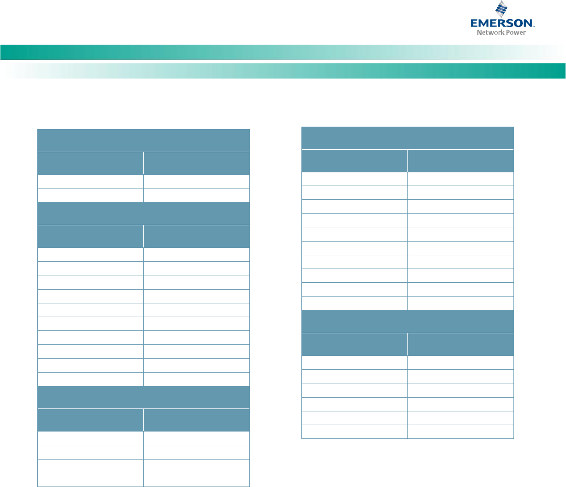
Table 2. System Interface Circuit Cards Signals Available on TB5
RS-485 (System External Interface Circuit Card)
Signal
TB5
RS-485 (+)
1
RS-485 (-)
2
OPT (System Internal Interface Circuit Card)
Signal
TB5
Battery 2 Shunt (-)
3
Battery 2 Shunt (+)
4
Load Shunt (-)
5
Load Shunt (+)
6
LVD2 Sense (-)
7
LVD2 Drive (+)
8
SPD (-)
not available
LVD2 Drive (-)
9
SPD (+)
not available
LVD2 Sense (+)
10
BA (System Internal Interface Circuit Card)
Signal
TB5
Battery Fuse Alarm 1
11
Battery Fuse Alarm 2
12
Battery Fuse Alarm 3
not available
Battery Fuse Alarm 4
not available
LA (System Internal Interface Circuit Card)
Signal
TB5
Load Fuse Alarm 1
13
Load Fuse Alarm 2
14
Load Fuse Alarm 3
15
Load Fuse Alarm 4
16
Load Fuse Alarm 5
not available
Load Fuse Alarm 6
not available
Load Fuse Alarm 7
not available
Load Fuse Alarm 8
not available
Load Fuse Alarm 9
not available
Load Fuse Alarm 10
not available
STD (System Internal Interface Circuit Card)
Signal
TB5
Battery 1 Shunt (-)
not available
LVD1 Drive (+)
not available
LVD1 Drive (-)
not available
Battery 1 Shunt (+)
not available
LVD1 Sense (-)
not available
LVD1 Sense (+)
not available