
Brochures and Data Sheets
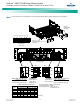
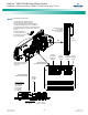
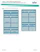
Table Of Contents
- Admonishments Used In This Document
- Important Safety Instructions
- Static Warning
- System Overview
- Installation Acceptance Checklist
- Installing the System
- General Requirements
- Securing the Relay Rack to the Floor
- Mounting System Components in a Relay Rack
- Setting Switch Options
- Making Electrical Connections
- Important Safety Instructions
- Wiring Considerations
- Relay Rack Grounding Connection (Frame Ground)
- AC Input and AC Input Equipment Grounding Connections to Rectifier Module Mounting Shelves
- External Alarm, Reference, Monitoring, and Control Connections
- ACU+ Controller Ethernet Connection (if required)
- -48V DC Output Connections
- Installing the Rectifier Modules and Initially Starting the System
- Installing the Rectifier Modules into Spec. No. 588705000 Rectifier Module Mounting Shelves
- Initially Starting, Configuring, and Checking System Operation
- Important Safety Instructions
- Initial Startup Preparation
- Initially Starting the System
- ACU+ Controller Initialization
- Verifying the Configuration File
- Checking Basic System Settings
- Changing Battery Capacity Rating in the ACU+
- Configuring the ACU+ Identification of Rectifiers and Assigning which Input Phase is Connected to the Rectifiers
- ACU+ Alarm Relay Check
- Checking System Status
- Final Steps
- Operating Procedures
- Maintenance
- Troubleshooting and Repair
- NetPerform™ Optimization Services
NetSure
™
-48V DC Bulk Output Power System
Installation and User Instructions, UM582127100 (Issue AA, May 7, 2013)
Spec. No: 582127100 UM582127100
Model No: 722NBBB Issue AA, May 7, 2013
19
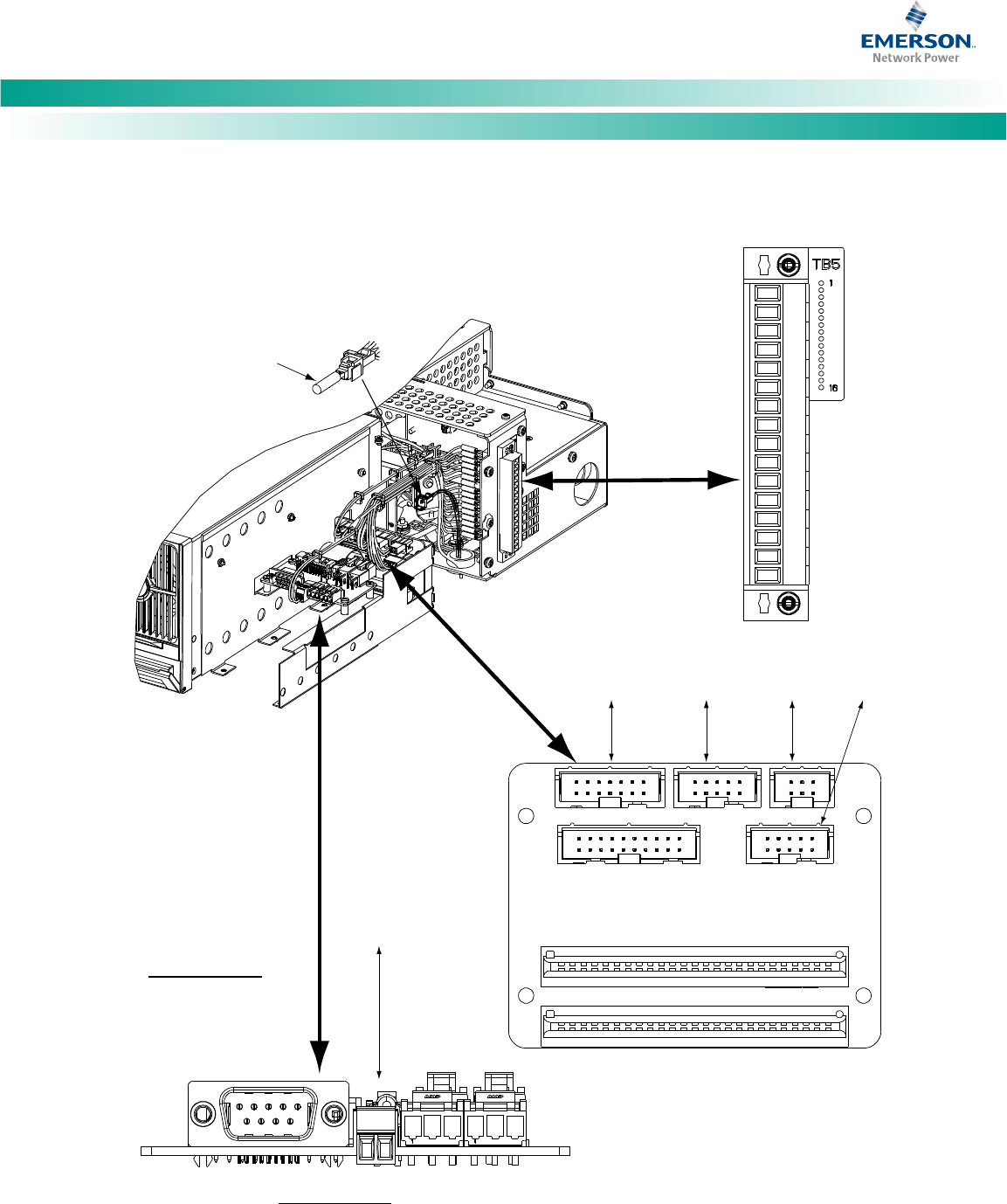
Figure 12. System Interface Connections
A CAN termination plug
must be installed if an
external device or system
is not connected here.
The end of the ACU+ CAN Bus is routed
from the bottom-most rectifier shelf into
the top-most rectifier shelf via cable P/N 556430.
Use cable P/N 556238 to connect external devices
to the end of the ACU+ CAN bus. Access the connector
by removing the top cover from the ACU+ section of
the shelf.
RS-485 Connection
Pin 1: RS485+
Pin 2: RS485-
RS-232 Connection
Pin 1: DCD232
Pin 2: RXD232
Pin 3: TXD232
Pin 4: DTR232
Pin 5: CGND
Pin 7: RTS232
RS-232 RS-485
SYSTEM
TEMP
PROBE 1
SYSTEM
TEMP
PROBE 2
1 5
6 9
21
1
2
1
2
1
2
1
2
1
2
STD
ACU+ Section of Main Shelf
(components removed for
clarity only)
Factory
Connected
to TB5
Internal System
Interface Circuit Card
TB5
External System
Interface Circuit Card
LA BA
OPT
Factory
Connected to
DC Bus and
CAN Bus
Factory
Connected
to TB5
See table
on next page.
Factory
Connected
to TB5
Factory
Connected
to TB5
Wire Size Capacity:
30-12 AWG.
Recommended Torque:
4.4 to 5.3 in-lbs.