
Brochures and Data Sheets
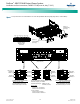
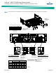
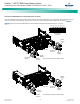
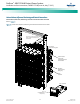
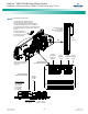
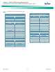
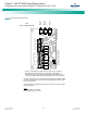
Table Of Contents
- Admonishments Used In This Document
- Important Safety Instructions
- Static Warning
- System Overview
- Installation Acceptance Checklist
- Installing the System
- General Requirements
- Securing the Relay Rack to the Floor
- Mounting System Components in a Relay Rack
- Setting Switch Options
- Making Electrical Connections
- Important Safety Instructions
- Wiring Considerations
- Relay Rack Grounding Connection (Frame Ground)
- AC Input and AC Input Equipment Grounding Connections to Rectifier Module Mounting Shelves
- External Alarm, Reference, Monitoring, and Control Connections
- ACU+ Controller Ethernet Connection (if required)
- -48V DC Output Connections
- Installing the Rectifier Modules and Initially Starting the System
- Installing the Rectifier Modules into Spec. No. 588705000 Rectifier Module Mounting Shelves
- Initially Starting, Configuring, and Checking System Operation
- Important Safety Instructions
- Initial Startup Preparation
- Initially Starting the System
- ACU+ Controller Initialization
- Verifying the Configuration File
- Checking Basic System Settings
- Changing Battery Capacity Rating in the ACU+
- Configuring the ACU+ Identification of Rectifiers and Assigning which Input Phase is Connected to the Rectifiers
- ACU+ Alarm Relay Check
- Checking System Status
- Final Steps
- Operating Procedures
- Maintenance
- Troubleshooting and Repair
- NetPerform™ Optimization Services

NetSure
™
-48V DC Bulk Output Power System
Installation and User Instructions, UM582127100 (Issue AA, May 7, 2013)
Spec. No: 582127100 UM582127100
Model No: 722NBBB Issue AA, May 7, 2013
14
Connections to 588705000 List 52 and 62 (Three-Phase,
Terminal Blocks)
Spec. No. 588705000 List 52 and 62 rectifier module mounting
shelf provides two 3-phase AC input connections. Each phase of
each input circuit supplies one rectifier module.
Refer to Figure 9 as this procedure is performed.
Note: Repeat the following procedure for each rectifier module
mounting shelf in the power system.
Accessing Connections and Wire Routing
1. Remove the two AC input access covers from the rear of
the rectifier module mounting shelf by first removing the
screws that secure them.
2. Install conduit fittings in the side or rear openings as
required. Plug buttons are provided, and must be
installed in the openings not being used.
3. Route wiring into the shelf through the previously
installed conduit fittings.
Making AC Input Connections
Note: In each shelf, rectifier module mounting positions are number
1-6 from left to right as viewed from the front. Note that in the
main shelf, the 6th position is occupied by the ACU+
Controller.
1. Make AC input connections as shown in Figure 9.
Connect each wire by inserting the stripped end into the
wire opening, and then tightening the screw. Torque
connections to value shown in Figure 9.
Making AC Equipment Grounding Connections
Note: Make equipment grounding connections to earth ground, not
to the branch circuit neutral conductor.
1. Connect AC input equipment grounding leads to the
frame ground studs using installer-provided ring lugs and
factory-supplied mounting hardware. Torque
connections to value shown in Figure 9.
Reinstalling Covers
1. After all AC input and equipment grounding connections
have been made and checked, reinstall the two AC input
access covers on the back of the shelf. Secure with the
previously removed screws.