
Brochures and Data Sheets
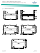

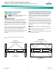
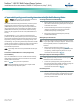
Table Of Contents
- Admonishments Used In This Document
- Important Safety Instructions
- Static Warning
- System Overview
- Installation Acceptance Checklist
- Installing the System
- General Requirements
- Securing the Relay Rack to the Floor
- Mounting System Components in a Relay Rack
- Setting Switch Options
- Making Electrical Connections
- Important Safety Instructions
- Wiring Considerations
- Relay Rack Grounding Connection (Frame Ground)
- AC Input and AC Input Equipment Grounding Connections to Rectifier Module Mounting Shelves
- External Alarm, Reference, Monitoring, and Control Connections
- ACU+ Controller Ethernet Connection (if required)
- -48V DC Output Connections
- Installing the Rectifier Modules and Initially Starting the System
- Installing the Rectifier Modules into Spec. No. 588705000 Rectifier Module Mounting Shelves
- Initially Starting, Configuring, and Checking System Operation
- Important Safety Instructions
- Initial Startup Preparation
- Initially Starting the System
- ACU+ Controller Initialization
- Verifying the Configuration File
- Checking Basic System Settings
- Changing Battery Capacity Rating in the ACU+
- Configuring the ACU+ Identification of Rectifiers and Assigning which Input Phase is Connected to the Rectifiers
- ACU+ Alarm Relay Check
- Checking System Status
- Final Steps
- Operating Procedures
- Maintenance
- Troubleshooting and Repair
- NetPerform™ Optimization Services
NetSure
™
-48V DC Bulk Output Power System
Installation and User Instructions, UM582127100 (Issue AA, May 7, 2013)
Spec. No: 582127100 UM582127100
Model No: 722NBBB Issue AA, May 7, 2013
11
Making Electrical Connections
Important Safety Instructions
Danger! Adhere to the “Important Safety Instructions”
presented at the front of this document.
Wiring Considerations
All wiring and branch circuit protection should follow the current
edition of the American National Standards Institute (ANSI)
approved National Fire Protection Association's (NFPA) National
Electrical Code (NEC), and applicable local codes. For operation in
countries where the NEC is not recognized, follow applicable
codes.
For wire size, branch circuit protection, crimp lug, and general
wiring recommendations; refer to System Application Guide
SAG582127100 and Power Data Sheet PD588705000.
Refer to drawing 031110100 for lug crimping information. Refer
to drawings 031110200 and 031110300 for additional lug
information.
Relay Rack Grounding Connection (Frame Ground)
For relay rack grounding requirements, refer to the current edition
of the American National Standards Institute (ANSI) approved
National Fire Protection Association's (NFPA) National Electrical
Code (NEC), applicable local codes, and your specific site
requirements.
A customer's grounding network lead can be attached to the top
of the relay rack. Provision is made for installing a lead with a two-
hole lug that has 1/4" bolt clearance holes on 5/8" centers. When
using 1/4-inch hardware, recommended torque is 84 in-lbs when a
standard flat washer and lock washer are used. Refer to Figure 7
for locations.
Note: REMOVE TAPE FROM HOLE LOCATIONS BEFORE INSTALLING
LUG.
Note: The DC return connection to this system can remain isolated
from system frame and chassis (DC-I).
Note: This system is suitable for installation as part of the Common
Bonding Network (CBN).
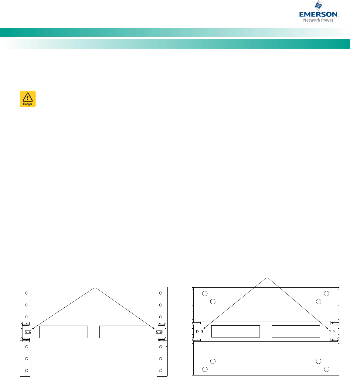
Figure 7. Relay Rack Frame Grounding Connection Points
Frame Ground
Connection Point
(1/4” clearance holes on 5/8” centers)
Frame Ground
Connection Point
(1/4” clearance holes on 5/8” centers)
Top View
(Typical Relay Rack)
Top View
(Typical Relay Rack)