
Brochures and Data Sheets
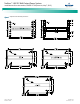
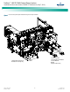

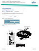
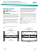
Table Of Contents
- Admonishments Used In This Document
- Important Safety Instructions
- Static Warning
- System Overview
- Installation Acceptance Checklist
- Installing the System
- General Requirements
- Securing the Relay Rack to the Floor
- Mounting System Components in a Relay Rack
- Setting Switch Options
- Making Electrical Connections
- Important Safety Instructions
- Wiring Considerations
- Relay Rack Grounding Connection (Frame Ground)
- AC Input and AC Input Equipment Grounding Connections to Rectifier Module Mounting Shelves
- External Alarm, Reference, Monitoring, and Control Connections
- ACU+ Controller Ethernet Connection (if required)
- -48V DC Output Connections
- Installing the Rectifier Modules and Initially Starting the System
- Installing the Rectifier Modules into Spec. No. 588705000 Rectifier Module Mounting Shelves
- Initially Starting, Configuring, and Checking System Operation
- Important Safety Instructions
- Initial Startup Preparation
- Initially Starting the System
- ACU+ Controller Initialization
- Verifying the Configuration File
- Checking Basic System Settings
- Changing Battery Capacity Rating in the ACU+
- Configuring the ACU+ Identification of Rectifiers and Assigning which Input Phase is Connected to the Rectifiers
- ACU+ Alarm Relay Check
- Checking System Status
- Final Steps
- Operating Procedures
- Maintenance
- Troubleshooting and Repair
- NetPerform™ Optimization Services

NetSure
™
-48V DC Bulk Output Power System
Installation and User Instructions, UM582127100 (Issue AA, May 7, 2013)
Spec. No: 582127100 UM582127100
Model No: 722NBBB Issue AA, May 7, 2013
8
Interconnecting the Rectifier Module Mounting Shelves CAN Bus
Each Spec. No. 588705000 rectifier module mounting shelf in the
system is daisy-chained to the controller. An ACU+ CAN Bus
connector is located at the top of each shelf and another at the
bottom of each shelf. These connectors are used to interconnect
the shelves to the controller. Refer to Figure 5 for connector
locations. These connections are factory made for shelves factory
installed. These connections must be made if a rectifier module
mounting shelf(s) is field installed.
The top connector of the top most rectifier module
mounting shelf (main shelf) is internally connected to the
controller.
The bottom connector of a shelf plugs into the top
connector on the shelf below it.
The bottom connector on the bottom most shelf must be
terminated with a termination plug.
PROCEDURE
Note: Refer to Figure 5 as this procedure is performed.
1. Connect the bottom connector on the main shelf to the
top connector on the 1st expansion shelf.
2. Connect the bottom connector on the 1st expansion
shelf to the top connector on the 2nd expansion shelf.
3. Connect the bottom connector on the 2nd expansion
shelf to the top connector on the 3rd expansion shelf.
4. Connect the bottom connector on the 3rd expansion
shelf to the top connector on the 4th expansion shelf.
5. Connect the bottom connector on the 4th expansion
shelf (or bottom-most shelf for systems with less than
four expansion shelves) to CAN Bus Jumper P/N 556430.
Route CAN Bus Jumper P/N 556430 within the interiors of
the shelves to the controller area in the main shelf.
Terminate CAN Bus Jumper P/N 556430 with termination
plug P/N 556273.