
Brochures and Data Sheets
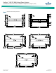
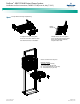
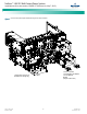

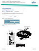
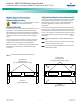
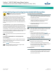
Table Of Contents
- Admonishments Used In This Document
- Important Safety Instructions
- Static Warning
- System Overview
- Installation Acceptance Checklist
- Installing the System
- General Requirements
- Securing the Relay Rack to the Floor
- Mounting System Components in a Relay Rack
- Setting Switch Options
- Making Electrical Connections
- Important Safety Instructions
- Wiring Considerations
- Relay Rack Grounding Connection (Frame Ground)
- AC Input and AC Input Equipment Grounding Connections to Rectifier Module Mounting Shelves
- External Alarm, Reference, Monitoring, and Control Connections
- ACU+ Controller Ethernet Connection (if required)
- -48V DC Output Connections
- Installing the Rectifier Modules and Initially Starting the System
- Installing the Rectifier Modules into Spec. No. 588705000 Rectifier Module Mounting Shelves
- Initially Starting, Configuring, and Checking System Operation
- Important Safety Instructions
- Initial Startup Preparation
- Initially Starting the System
- ACU+ Controller Initialization
- Verifying the Configuration File
- Checking Basic System Settings
- Changing Battery Capacity Rating in the ACU+
- Configuring the ACU+ Identification of Rectifiers and Assigning which Input Phase is Connected to the Rectifiers
- ACU+ Alarm Relay Check
- Checking System Status
- Final Steps
- Operating Procedures
- Maintenance
- Troubleshooting and Repair
- NetPerform™ Optimization Services
NetSure
™
-48V DC Bulk Output Power System
Installation and User Instructions, UM582127100 (Issue AA, May 7, 2013)
Spec. No: 582127100 UM582127100
Model No: 722NBBB Issue AA, May 7, 2013
5
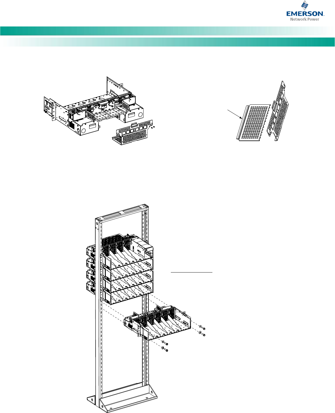
Figure 2. Rectifier Module Mounting Shelf Mounting
Front
If multiple shelves are in the system,
remove the rear center shield from each.
Save hardware for later re-installation.
If multiple shelves are in the system,
remove and discard the bottom section
of rear center shield for all shelves
except the bottom shelf.
Rear
Bottom
Section
Secure each shelf to the relay rack.
Mounting Hardware
12-24 x 3/4" Thread Forming
Hex Head Screw (two per side)
No. 10/12 Ground Washer (one per side)
No. 12 Flat Washer (one per side)