
Brochures and Data Sheets
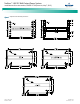
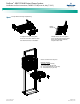
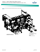

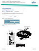
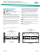
Table Of Contents
- Admonishments Used In This Document
- Important Safety Instructions
- Static Warning
- System Overview
- Installation Acceptance Checklist
- Installing the System
- General Requirements
- Securing the Relay Rack to the Floor
- Mounting System Components in a Relay Rack
- Setting Switch Options
- Making Electrical Connections
- Important Safety Instructions
- Wiring Considerations
- Relay Rack Grounding Connection (Frame Ground)
- AC Input and AC Input Equipment Grounding Connections to Rectifier Module Mounting Shelves
- External Alarm, Reference, Monitoring, and Control Connections
- ACU+ Controller Ethernet Connection (if required)
- -48V DC Output Connections
- Installing the Rectifier Modules and Initially Starting the System
- Installing the Rectifier Modules into Spec. No. 588705000 Rectifier Module Mounting Shelves
- Initially Starting, Configuring, and Checking System Operation
- Important Safety Instructions
- Initial Startup Preparation
- Initially Starting the System
- ACU+ Controller Initialization
- Verifying the Configuration File
- Checking Basic System Settings
- Changing Battery Capacity Rating in the ACU+
- Configuring the ACU+ Identification of Rectifiers and Assigning which Input Phase is Connected to the Rectifiers
- ACU+ Alarm Relay Check
- Checking System Status
- Final Steps
- Operating Procedures
- Maintenance
- Troubleshooting and Repair
- NetPerform™ Optimization Services
NetSure
™
-48V DC Bulk Output Power System
Installation and User Instructions, UM582127100 (Issue AA, May 7, 2013)
Spec. No: 582127100 UM582127100
Model No: 722NBBB Issue AA, May 7, 2013
3
Mounting the Rectifier Module Mounting Shelf(s) to a Relay
Rack
Danger! The relay rack must be securely anchored to the
floor before the rectifier module mounting shelf(s) is
installed.
Note: If the system was shipped on shipping rails, rectifier module
mounting shelves are installed in groups of two or less. Space
has been provided for pallet forks to fit between the sets of
rectifier module mounting shelves. Simply rest the pallet forks
on the bottom-most rectifier module mounting shelf, unbolt
the shelves from the shipping rails, transfer the shelves to the
relay rack, and resecure the shelves to the relay rack.
Note: Refer to Figure 2 as this procedure is performed.
PROCEDURE
1. If multiple shelves are in the system, remove the rear
center shield from each. Save hardware for later re-
installation.
2. If multiple shelves are in the system, remove and discard
the bottom section of the rear center shield from all
shelves except the bottom shelf.
Note: In multiple shelf systems, apply electrical anti-oxidizing
compound to busbar mating surfaces before performing
the next step.
3. Position the rectifier module mounting shelf in the relay
rack. In multiple shelf systems, align the holes in the
mating busbars before securing the shelves to the relay
rack.
Note: Install the ground washers in the next step so the teeth
dig into the paint on the mounting angles.
4. Secure the rectifier module mounting shelf to the relay
rack. Torque all screws to 65 in-lbs.
Hardware build-up is:
12-24 x 3/4" screw and flat washer,
(1) set per side.
12-24 x 3/4" screw and ground washer,
(1) set per side.
5. Repeat for any additional rectifier module mounting
shelf. Rectifier module mounting shelves are install
directly below each other with no space between them.
The main shelf (the one with the ACU+ Controller) should
be the top-most shelf.
Interconnecting the Rectifier Module Mounting Shelves
Output Busbars in Multiple Shelf Systems
Note: Refer to Figure 3 as this procedure is performed.
PROCEDURE
1. The mating busbars are factory installed on the
expansion rectifier module mounting shelf. Secure these
busbars to the output busbars on the shelf above it.
Hardware is provided with the expansion rectifier module
mounting shelf.
Hardware build-up for these connections are:
1/4-20 x 7/8" Bolt,
1/4" Belleville Lock Washer,
1/4" Flat Washer.
Install the Belleville lock washer so the concave side is
towards the busbar. Torque all connections to 60 in-lbs.
Note: Some systems may come with two shelves connected
together with a common relay rack mounting bracket
and an output busbar spanning both shelves. Connect
these shelves to other shelves in the same manner as
described here.
2. Repeat this procedure for each expansion rectifier
module mounting shelf.
Changing the Direction of the DC Output Cables
DC output cables can either enter from the right, from the left, or
from the rear. To reconfigure the shelf for these options, remove
the appropriate shield and position the DC output busbars per the
following procedure. The DC output busbars are factory
connected for DC output cables entering from the right as viewed
from the front.
PROCEDURE
Note: Refer to Figure 4 as this procedure is performed.
1. In Figure 4, select the view for your DC output cabling
requirements (left, right, or rear).
2. Remove the appropriate shield as required as shown in
the selected view.
3. Reposition the DC output lug landing busbars as shown in
the selected view.