
Brochures and Data Sheets

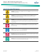

Table Of Contents
- Admonishments Used In This Document
- Important Safety Instructions
- Static Warning
- System Overview
- Installation Acceptance Checklist
- Installing the System
- General Requirements
- Securing the Relay Rack to the Floor
- Mounting System Components in a Relay Rack
- Setting Switch Options
- Making Electrical Connections
- Important Safety Instructions
- Wiring Considerations
- Relay Rack Grounding Connection (Frame Ground)
- AC Input and AC Input Equipment Grounding Connections to Rectifier Module Mounting Shelves
- External Alarm, Reference, Monitoring, and Control Connections
- ACU+ Controller Ethernet Connection (if required)
- -48V DC Output Connections
- Installing the Rectifier Modules and Initially Starting the System
- Installing the Rectifier Modules into Spec. No. 588705000 Rectifier Module Mounting Shelves
- Initially Starting, Configuring, and Checking System Operation
- Important Safety Instructions
- Initial Startup Preparation
- Initially Starting the System
- ACU+ Controller Initialization
- Verifying the Configuration File
- Checking Basic System Settings
- Changing Battery Capacity Rating in the ACU+
- Configuring the ACU+ Identification of Rectifiers and Assigning which Input Phase is Connected to the Rectifiers
- ACU+ Alarm Relay Check
- Checking System Status
- Final Steps
- Operating Procedures
- Maintenance
- Troubleshooting and Repair
- NetPerform™ Optimization Services

NetSure
™
-48V DC Bulk Output Power System
Installation and User Instructions, UM582127100 (Issue AA, May 7, 2013)
Spec. No: 582127100 UM582127100
Model No: 722NBBB Issue AA, May 7, 2013
2
Note: Some of these procedures may have been performed at the
factory for you.
Installing the System
Relay Rack Secured to Floor
System Components Mounted in Relay Rack and
Interconnected (if required)
Setting Switch Options
Factory Switch Setting on IB2 Interface Board Verified
Making Electrical Connections
Relay Rack Grounding Connection (Frame Ground) Made
AC Input and AC Input Equipment Grounding
Connections Made
External Alarm, Reference, Monitoring, and Control
Connections Made
ACU+ Controller Ethernet Connection Made (if required)
-48V DC Output Connections Made
Installing the Rectifier Modules and Initially Starting the
System
Rectifier Modules Installed
System Started, Configured, and Checked
Installing the System
General Requirements
This product is intended only for installation in a
restricted access location on or above a non-combustible
surface.
This product must be located in a controlled environment
with access to crafts persons only.
This product is intended for installation in network
telecommunication facilities (CO, vault, hut, or other
environmentally controlled electronic equipment
enclosure).
This product is intended for connection to the common
bonding network in a network telecommunication facility
(CO, vault, hut, or other environmentally controlled
electronic equipment enclosure).
The DC return connection to this system can remain
isolated from system frame and chassis (DC-I).
This system is suitable for installation as part of the
Common Bonding Network (CBN).
The installer should be familiar with the installation
requirements and techniques to be used in securing the
relay rack to the floor.
Rectifier and rectifier module mounting shelf ventilating
openings must not be blocked and temperature of air
entering rectifiers must not exceed rated operating
ambient temperature range found in SAG582127100.
Clearance requirements are:
a. Recommended minimum aisle space clearance for
the front of each bay is 2' 6".
b. Minimum spacing from the rear of the bay to a wall
or other solid surface is that which is specified for
proper rectifier module mounting shelf ventilation.
Refer to the rectifier module mounting shelf Power
Data Sheet for ventilation spacing requirements.
Note: Minimum rear spacing specified for ventilation
may not permit installation and maintenance
of the system.
Recommended minimum aisle space clearance for
the rear of each bay is 2’ 0” to allow for installation
and maintenance.
Securing the Relay Rack to the Floor
Secure the relay rack to the floor per site requirements. Refer to
“General Requirements” on page 2.
Ventilation Requirements
Refer to the “General Requirements” on page 2.
Relay Rack Floor Mounting Dimensions
Refer to Figure 1 for relay rack floor mounting dimensions.
Mounting System Components in a Relay Rack
Note: If the power system was ordered in a relay rack, these
procedures have been performed at the factory.
This power system is designed to mount in a standard 23” relay
rack having 1” or 1-3/4” multiple drillings. Refer to System
Application Guide SAG582127100 for overall dimensions and a list
of available relay racks.