NetSure™ -48V DC Bulk Output Power System Installation and User Instructions, UM582127100 (Issue AA, May 7, 2013) Specification Number: 582127100 Model Number: 722NBBB
NetSure™ -48V DC Bulk Output Power System Installation and User Instructions, UM582127100 (Issue AA, May 7, 2013) This page is intentionally blank. Spec.
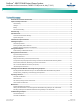
NetSure™ -48V DC Bulk Output Power System Installation and User Instructions, UM582127100 (Issue AA, May 7, 2013) Table of Contents Admonishments Used In This Document............................................................................................................... iii Important Safety Instructions .............................................................................................................................. iv General Safety .....................................................
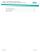
NetSure™ -48V DC Bulk Output Power System Installation and User Instructions, UM582127100 (Issue AA, May 7, 2013) ACU+ Controller Configuration .............................................................................................................................. 36 System Troubleshooting Information .................................................................................................................... 36 Replacement Information ..........................................................
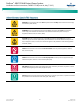
NetSure™ -48V DC Bulk Output Power System Installation and User Instructions, UM582127100 (Issue AA, May 7, 2013) Admonishments Used In This Document DANGER! Warns of a hazard the reader will be exposed to that will likely result in death or serious injury if not avoided. (ANSI, OSHA) WARNING! Warns of a potential hazard the reader may be exposed to that could result in death or serious injury if not avoided.
NetSure™ -48V DC Bulk Output Power System Installation and User Instructions, UM582127100 (Issue AA, May 7, 2013) Important Safety Instructions General Safety Battery DANGER! YOU MUST FOLLOW APPROVED SAFETY PROCEDURES. WARNING! Correct polarity must be observed when connecting battery leads. Performing the following procedures may expose you to hazards. These procedures should be performed by qualified technicians familiar with the hazards associated with this type of equipment.
NetSure™ -48V DC Bulk Output Power System Installation and User Instructions, UM582127100 (Issue AA, May 7, 2013) Static Warning The printed circuit cards used in this equipment contain static sensitive components. The warnings listed below must be observed to prevent damage to these components. Disregarding any of these warnings may result in personal injury or damage to the equipment. 1. Strictly adhere to the procedures provided in this document. 2.
NetSure™ -48V DC Bulk Output Power System Installation and User Instructions, UM582127100 (Issue AA, May 7, 2013) This page is intentionally blank. Spec.
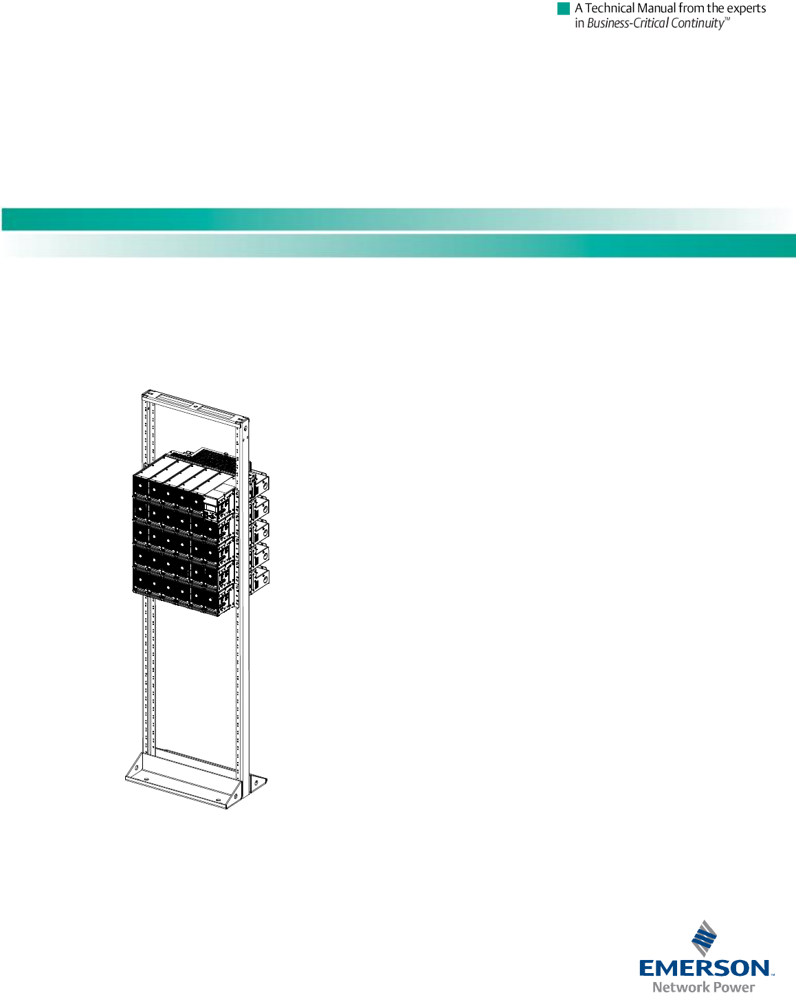
NetSure™ -48V DC Bulk Output Power System Installation and User Instructions, UM582127100 (Issue AA, May 7, 2013) System Overview Customer Documentation Package Main Rectifier Module Mounting Shelf This document (UM582127100) provides Installation and User Instructions for NetSure™ -48V DC Bulk Output Power System Model 722NBBB, Spec. No. 582127100. The system contains a main rectifier module mounting shelf.
NetSure™ -48V DC Bulk Output Power System Installation and User Instructions, UM582127100 (Issue AA, May 7, 2013) Note: Some of these procedures may have been performed at the factory for you. This system is suitable for installation as part of the Common Bonding Network (CBN). Installing the System The installer should be familiar with the installation requirements and techniques to be used in securing the relay rack to the floor.
NetSure™ -48V DC Bulk Output Power System Installation and User Instructions, UM582127100 (Issue AA, May 7, 2013) Mounting the Rectifier Module Mounting Shelf(s) to a Relay Rack Interconnecting the Rectifier Module Mounting Shelves Output Busbars in Multiple Shelf Systems Danger! The relay rack must be securely anchored to the floor before the rectifier module mounting shelf(s) is installed.
NetSure™ -48V DC Bulk Output Power System Installation and User Instructions, UM582127100 (Issue AA, May 7, 2013) Figure 1. Relay Rack Floor Mounting Dimensions Spec.
NetSure™ -48V DC Bulk Output Power System Installation and User Instructions, UM582127100 (Issue AA, May 7, 2013) Figure 2. Rectifier Module Mounting Shelf Mounting Bottom Section Rear If multiple shelves are in the system, remove the rear center shield from each. If multiple shelves are in the system, remove and discard the bottom section of rear center shield for all shelves except the bottom shelf. Save hardware for later re-installation. Secure each shelf to the relay rack.
NetSure™ -48V DC Bulk Output Power System Installation and User Instructions, UM582127100 (Issue AA, May 7, 2013) Figure 3. Interconnecting the Rectifier Module Mounting Shelves Output Busbars Components removed in illustration for clarity only. Spec. No: 582127100 Model No: 722NBBB 1/4-20 x 7/8” Bolt 1/4” Belleville Lock Washer 1/4” Flat Washer Busbar (Torque to 60 in-lbs.
NetSure™ -48V DC Bulk Output Power System Installation and User Instructions, UM582127100 (Issue AA, May 7, 2013) Figure 4. Changing the Direction of the DC Output Cables DC Output Cables Entering from the Right (as viewed from the front) DC Output Cables Entering from the Left (as viewed from the front) References to left and right are as viewed from the front. Right side shield removed. Rear-bottom shield not shown. Left side shield removed. Rear-bottom shield not shown.
NetSure™ -48V DC Bulk Output Power System Installation and User Instructions, UM582127100 (Issue AA, May 7, 2013) Interconnecting the Rectifier Module Mounting Shelves CAN Bus Each Spec. No. 588705000 rectifier module mounting shelf in the system is daisy-chained to the controller. An ACU+ CAN Bus connector is located at the top of each shelf and another at the bottom of each shelf. These connectors are used to interconnect the shelves to the controller. Refer to Figure 5 for connector locations.
NetSure™ -48V DC Bulk Output Power System Installation and User Instructions, UM582127100 (Issue AA, May 7, 2013) Figure 5. Control Bus Connections between Controller and Rectifier Module Mounting Shelves Spec. No. 588705000 Route CAN Bus Jumper P/N 556430 into this area. Secure with cable ties. Connect termination plug P/N 556273 to open end. Alarm & Control Connections Between Shelves and Controller Exploded View Shown to Illustrate Wire Connections Only These two connectors are plugged together.
NetSure™ -48V DC Bulk Output Power System Installation and User Instructions, UM582127100 (Issue AA, May 7, 2013) Setting Switch Options Switch Settings on IB2 Interface Board Dip Switch SW1 on the IB2 board is used to set the communications address for this board. Refer to Table 1 for SW1 settings. Refer to Figure 6 for SW1 location. Perform the following procedure to verify the factory settings. This procedure can also be used to make adjustments on a replacement circuit card. PROCEDURE 1. Table 1.
NetSure™ -48V DC Bulk Output Power System Installation and User Instructions, UM582127100 (Issue AA, May 7, 2013) Making Electrical Connections Relay Rack Grounding Connection (Frame Ground) Important Safety Instructions For relay rack grounding requirements, refer to the current edition of the American National Standards Institute (ANSI) approved National Fire Protection Association's (NFPA) National Electrical Code (NEC), applicable local codes, and your specific site requirements.
NetSure™ -48V DC Bulk Output Power System Installation and User Instructions, UM582127100 (Issue AA, May 7, 2013) AC Input and AC Input Equipment Grounding Connections to Rectifier Module Mounting Shelves Danger! Adhere to the “Important Safety Instructions” presented at the front of this document.
NetSure™ -48V DC Bulk Output Power System Installation and User Instructions, UM582127100 (Issue AA, May 7, 2013) Figure 8. AC Input Connections to a 588705000 List 51 and 61 Rectifier Module Mounting Shelf (Single-Phase, Terminal Blocks) Hole for 1" Conduit Fitting (AC Input) Rear View (List 51 shown) Rect. Rect. Rect. Rect. Rect. Rect.
NetSure™ -48V DC Bulk Output Power System Installation and User Instructions, UM582127100 (Issue AA, May 7, 2013) Connections to 588705000 List 52 and 62 (Three-Phase, Terminal Blocks) Spec. No. 588705000 List 52 and 62 rectifier module mounting shelf provides two 3-phase AC input connections. Each phase of each input circuit supplies one rectifier module. Making AC Input Connections Note: In each shelf, rectifier module mounting positions are number 1-6 from left to right as viewed from the front.
NetSure™ -48V DC Bulk Output Power System Installation and User Instructions, UM582127100 (Issue AA, May 7, 2013) Figure 9. AC Input Connections to a 588705000 List 52 and 62 Rectifier Module Mounting Shelf (Three-Phase, Terminal Blocks) Hole for 1" Conduit Fitting (AC Input) Rear View (List 52 shown) Rect. Rect. Rect. Rect. Rect. Rect.
NetSure™ -48V DC Bulk Output Power System Installation and User Instructions, UM582127100 (Issue AA, May 7, 2013) Connections to 588705000 List 53 and 63 (Single-Phase, Line Cords) Spec. No. 588705000 List 53 and 63 rectifier module mounting shelf is provided with five (5) or six (6) factory installed AC input line cords (one for each rectifier module position). Plug each AC line cord into a properly wired AC outlet or distribution box. Refer to Figure 10. Figure 10.
NetSure™ -48V DC Bulk Output Power System Installation and User Instructions, UM582127100 (Issue AA, May 7, 2013) External Alarm, Reference, Monitoring, and Control Connections External Alarm, Reference, Monitoring, and Control Connection Points Locations Refer to Figure 11. Figure 11. External Alarm, Reference, Monitoring, and Control Connection Points Locations Top cover can be removed from ACU+ section to facilitate circuit card access.
NetSure™ -48V DC Bulk Output Power System Installation and User Instructions, UM582127100 (Issue AA, May 7, 2013) System Interface Circuit Cards Connections (if required) Mounted in the main rectifier module mounting shelf is a system internal interface circuit card and a system external interface circuit card. Factory cabling is routed from the system interface circuit cards to terminal block TB5.
NetSure™ -48V DC Bulk Output Power System Installation and User Instructions, UM582127100 (Issue AA, May 7, 2013) Figure 12. System Interface Connections The end of the ACU+ CAN Bus is routed from the bottom-most rectifier shelf into the top-most rectifier shelf via cable P/N 556430. Use cable P/N 556238 to connect external devices to the end of the ACU+ CAN bus. Access the connector by removing the top cover from the ACU+ section of the shelf. Wire Size Capacity: 30-12 AWG. Recommended Torque: 4.4 to 5.
NetSure™ -48V DC Bulk Output Power System Installation and User Instructions, UM582127100 (Issue AA, May 7, 2013) Table 2.
NetSure™ -48V DC Bulk Output Power System Installation and User Instructions, UM582127100 (Issue AA, May 7, 2013) The relays may be preprogrammed for specific functions. Refer to the configuration drawing (C-drawing) supplied with your system for your system’s specific configuration. IB2 (ACU+ Interface Board) Connections (if required) The IB2 (ACU+ Interface Board) provides connection points for digital inputs, programmable relay outputs, and temperature probes.
NetSure™ -48V DC Bulk Output Power System Installation and User Instructions, UM582127100 (Issue AA, May 7, 2013) IB2 Board (Top View) Connector to ACU+ 8 7 6 5 4 3 2 1 2 4 1 6 3 2 5 4 1 6 3 2 5 4 1 6 3 Switch settings must be in this position to interface with the ACU+ Controller SW1 RELAY 2 4 6 8 6 4 2 6 4 2 6 4 2 6 4 2 5 1 3 5 1 3 5 1 3 5 1 3 NO C NC NO C NC NO C NC NO C NC 5 NO C NC NO C NC NO C NC NO C NC * 1 3 5 7 Relay Output Terminal Blocks J9 J8 J7 J6 Digit
NetSure™ -48V DC Bulk Output Power System Installation and User Instructions, UM582127100 (Issue AA, May 7, 2013) Table 3. Programmable Digital Inputs – IB2 Programmable Digital Input 1 2 3 4 5 6 7 8 IB2 Pin No. Factory Wiring Default Digital Input Function The digital inputs may be preprogrammed for specific functions and have factory wiring connected. Refer to the configuration drawing (C-drawing) supplied with your system for your system’s specific configuration.
NetSure™ -48V DC Bulk Output Power System Installation and User Instructions, UM582127100 (Issue AA, May 7, 2013) Table 4. Programmable Relay Outputs – IB2 Programmable Relay Output 1 2 3 4 5 6 7 8 IB2 Pin No.
NetSure™ -48V DC Bulk Output Power System Installation and User Instructions, UM582127100 (Issue AA, May 7, 2013) ACU+ Controller CAN Bus PROCEDURE The end of the ACU+ CAN Bus is routed into the ACU+ section of the main rectifier module mounting shelf via cable P/N 556430. Use cable P/N 556238 to connect external devices to the end of the ACU+ CAN bus. Access the ACU+ CAN Bus connector by removing the top cover from the ACU+ section of the main rectifier module mounting shelf.
NetSure™ -48V DC Bulk Output Power System Installation and User Instructions, UM582127100 (Issue AA, May 7, 2013) Table 6.
NetSure™ -48V DC Bulk Output Power System Installation and User Instructions, UM582127100 (Issue AA, May 7, 2013) Figure 14. -48V DC Output Connections -48V DC OUTPUT CONNECTIONS 3/8 Clearance Holes on 1” Centers (Customer must order or supply lug mounting hardware.) Maximum Lug Width: 1.31” for three (3) lugs per polarity. 1.78” for two (2) lugs per polarity. DC Output Connection Options 1. Route cables left, right, or out the back by repositioning the lug landing busbars. 2.
NetSure™ -48V DC Bulk Output Power System Installation and User Instructions, UM582127100 (Issue AA, May 7, 2013) Figure 15. Typical Lug Layout Diagrams Three (3) Lugs Layout Diagram Maximum Lug Tab Width: 1.31” Two (2) Lugs Layout Diagram Maximum Lug Tab Width: 1.78” Spec.
NetSure™ -48V DC Bulk Output Power System Installation and User Instructions, UM582127100 (Issue AA, May 7, 2013) Installing the Rectifier Modules and Initially Starting the System Installing the Rectifier Modules into Spec. No. 588705000 Rectifier Module Mounting Shelves Rectifier modules can be inserted or removed with power applied (hot swappable). 7. Repeat the above steps for each rectifier module being installed in the system. 8.
NetSure™ -48V DC Bulk Output Power System Installation and User Instructions, UM582127100 (Issue AA, May 7, 2013) Initially Starting the System 2. Next, the language screen appears. Press the up or down arrow key to select the desired language. Press the ENT key to confirm the selection. If no key is pressed within 10 seconds, the ACU+ selects the displayed language automatically. 3. As initialization continues, the Main screen is displayed, but with zero volts. Initialization is not complete. 4.
NetSure™ -48V DC Bulk Output Power System Installation and User Instructions, UM582127100 (Issue AA, May 7, 2013) PROCEDURE Verifying the Configuration File Your ACU+ was programmed with a configuration file that sets all adjustable parameters. The version number of the configuration file can be found on the configuration drawing (C-drawing) that is supplied with your power system documentation, and on a label located on the ACU+.
NetSure™ -48V DC Bulk Output Power System Installation and User Instructions, UM582127100 (Issue AA, May 7, 2013) Table 7.
NetSure™ -48V DC Bulk Output Power System Installation and User Instructions, UM582127100 (Issue AA, May 7, 2013) Upon power up, the ACU+ arbitrarily assigns Phase A, B, or C to each rectifier. This assignment is used to display rectifier AC input phase voltage(s). The User may reassign the phase to each rectifier per your specific installation by following the procedure below. the up or down keys to change the phase connected to the flashing rectifier. Press ENT.
NetSure™ -48V DC Bulk Output Power System Installation and User Instructions, UM582127100 (Issue AA, May 7, 2013) Checking System Status Final Steps PROCEDURE 1. PROCEDURE Observe the status of the indicators located on the ACU+ and rectifiers. If the system is operating normally, the status of these is as shown in Table 8. Table 8. 1. Status and Alarm Indicators Component ACU+ Rectifier Modules Spec.
NetSure™ -48V DC Bulk Output Power System Installation and User Instructions, UM582127100 (Issue AA, May 7, 2013) Operating Procedures Table 9. Controller and Rectifiers For operation instructions on these units, refer to the following documents. PROCEDURE ACU+ Controller Instructions (UM1M820BNA) Rectifier Instructions (UM1R483500E) ESTOP Function If an ESTOP switch is wired to the ACU+ IB2 Interface Board, customer-furnished system ground applied to terminal DI8+ activates the ESTOP function.
NetSure™ -48V DC Bulk Output Power System Installation and User Instructions, UM582127100 (Issue AA, May 7, 2013) Troubleshooting and Repair Contact Information Support contact information is provided on the inside of the back cover of this document. Controller and Rectifiers For troubleshooting and repair instructions on these units, refer to the following documents.
NetSure™ -48V DC Bulk Output Power System Installation and User Instructions, UM582127100 (Issue AA, May 7, 2013) step and proceed to step 3. Otherwise, to enter a password, with the cursor at the User Name field (default is “Admin”), press the down arrow key to move cursor down to the password line. Press ENT. “0” is highlighted. Press the up arrow key once to change the “0” to”1” (default password is “1”), then press ENT twice.
NetSure™ -48V DC Bulk Output Power System Installation and User Instructions, UM582127100 (Issue AA, May 7, 2013) PROCEDURE 1. Performing this procedure may activate external alarms. Do one of the following. If possible, disable these alarms. If these alarms cannot be easily disabled, notify the appropriate personnel to disregard any future alarms associated with this system while the procedure is being performed. Connect an approved grounding strap to your wrist.
NetSure™ -48V DC Bulk Output Power System Installation and User Instructions, UM582127100 (Issue AA, May 7, 2013) Figure 18. IB2 (ACU+ Interface Board) Replacement Top cover can be removed from ACU+ section to facilitate replacement.
NetSure™ -48V DC Bulk Output Power System Installation and User Instructions, UM582127100 (Issue AA, May 7, 2013) This page is intentionally blank. Spec.
NetSure™ -48V DC Bulk Output Power System Installation and User Instructions, UM582127100 (Issue AA, May 7, 2013) NetPerform™ Optimization Services At Emerson Network Power, we understand the importance of reliable equipment – it’s critical to both your business and your bottom line. That is why we offer a wide array of services to meet all of your network infrastructure needs.
NetSure™ -48V DC Bulk Output Power System Installation and User Instructions, UM582127100 (Issue AA, April 25, 2013) Spec.