
Brochures and Data Sheets


SAG582127100 System Application Guide
Issue AA, May 7, 2013 Spec. No. 582127100 (Model 722NBBB)
Page 8 of 26
This document is property of Emerson Network Power, Energy Systems, North America, Inc. and contains confidential and proprietary information owned by Emerson Network Power, Energy
Systems, North America, Inc. Any copying, use, or disclosure of it without the written permission of Emerson Network Power, Energy Systems, North America, Inc. is strictly prohibited.
ACCESSORY DESCRIPTIONS
ACU+ (Advanced Control Unit Plus) Controller, P/N 1M820DNA
Features
Provides one (1) Model M820DNA, Spec. No. 1M820DNA system
controller.
Factory programmed with the configuration file required for the system
configuration ordered.
Note: For custom ACU+ configurations, contact Emerson.
Restrictions
Only one (1) controller per power system is required.
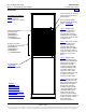
Mounts in the main rectifier mounting shelf.
Ordering Notes
1) Order one (1) ACU+ Controller (P/N 1M820DNA) per power system (to be installed in a main rectifier
module mounting shelf).
2) Order up to four (4) optional temperature probes for ambient and battery temperature monitoring, as
required. The temperature probe(s) may also be used for the battery charge temperature compensation
feature and BTRM (Battery Thermal Runaway Management). Refer to “Optional Temperature Probes” on
page 8 for additional information.
3) Order optional supervisory modules as desired (shipped loose).
SM-TEMP (Supervisory Module for Temperature Probes).
Note: A system can have up to (8) SM-Temp modules for a total of sixty-eight (68) temperature
probes that can be used in the power system for ambient and battery monitoring.
Optional Temperature Probes
Features
Up to two (2) temperature probes can be connected to the IB2 (ACU+ Interface Board). Up to two (2)
additional temperature probes can be connected to the System Interface Board. Any combination of the
four (4) temperature probes can be programmed to monitor ambient temperature and/or battery
temperature. A temperature probe set to monitor battery temperature can also be used for the rectifier
battery charge temperature compensation feature, or the battery charge temperature compensation
feature can be programmed to use the average or highest value of all battery temperature probes. The
battery charge temperature compensation feature allows the controller to automatically increase or
decrease the output voltage of the system to maintain battery float current as battery temperature
decreases or increases, respectively. Battery life can be extended when an optimum charge voltage to
the battery with respect to temperature is maintained. A temperature probe set to monitor battery
temperature can also be used for the BTRM (Battery Thermal Runaway Management) feature. The
BTRM feature lowers output voltage when a high temperature condition exists to control against battery
thermal runaway.
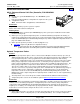
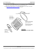
The temperature sensor end of the probe contains a tab with a 5/16” clearance hole for mounting.
Temperature probes can also be used with the optional SM-Temp Temperature Concentrator.
Restrictions
A temperature probe programmed to monitor battery temperature should be mounted on the negative post of
a battery cell to sense battery temperature. A temperature probe used for battery charge temperature
compensation and/or BTRM (Battery Thermal Runaway Management) should also be mounted on the
negative post of a battery cell. A temperature probe programmed to monitor ambient temperature should be
mounted in a convenient location, away from direct sources of heat or cold.
Ordering Notes
1) Order temperature probes as required. Note that each temperature probe consists of two pieces which
plug together to make a complete probe (see the following illustration). For a complete temperature
Home
Home