
Brochures and Data Sheets


System Application Guide SAG582127100
Spec. No. 582127100 (Model 722NBBB) Issue AA, May 7, 2013
Page 5 of 26
This document is property of Emerson Network Power, Energy Systems, North America, Inc. and contains confidential and proprietary information owned by Emerson Network Power, Energy
Systems, North America, Inc. Any copying, use, or disclosure of it without the written permission of Emerson Network Power, Energy Systems, North America, Inc. is strictly prohibited.
LIST DESCRIPTIONS
List Numbers
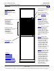
List 1: Common Equipment (Relay Rack or Rail Mounted System)
Features
Provides common equipment for one “bulk output” bay rated for up to 2000 amperes mounted in a relay
rack or on shipping brackets.
Ordering Notes
1) Order a relay rack or shipping brackets per “Relay Racks and Shipping Brackets” on page 11. If required,
order relay rack transition plates per “Transition Plates to Mount Relay Rack on Top of GNB Absolyte IIP
Batteries” on page 12.
2) Order interface components for the main rectifier module mounting shelf as required per List 10 or
interface components for the main rectifier module mounting shelf and one (1) expansion rectifier module
mounting shelf per List 20.
3) Order interface components for one (1) to four (4) expansion rectifier module mounting shelf(s) as
required per List 11 or interface components for an expansion rectifier module mounting shelf to an
expansion rectifier module mounting shelf per List 21. In systems using List 20 and List 21 interface
components, if a fourth expansion rectifier module mounting shelf is required, also order a List 11 for the
fourth expansion rectifier module mounting shelf.
List 2: Common Equipment (Ship Loose System)
Features
Provides common equipment for one “bulk output” bay rated for up to 2000 amperes to be mounted in a
customer rack.
Ordering Notes
1) Order interface components for the main rectifier module mounting shelf per List 10.
2) Order interface components for one (1) to four (4) expansion rectifier module mounting shelf(s) as
required per List 11.
List 10: Main Rectifier Module Mounting Shelf Interface Components
Features
Provides DC output lug landing busbar assemblies for the main rectifier module mounting shelf. Provides
shelf rack mounting hardware. The main rectifier module mounting shelf must be ordered separately.
Refer to Power Data Sheet PD588705000.
The main rectifier module mounting shelf provides a mounting slot for the ACU+ controller. Also provided
in the main rectifier module mounting shelf is the system interface board which provides customer
connections for two (2) external battery fuse alarm inputs, four (4) external load fuse alarm inputs, one (1)
load shunt input, one (1) battery shunt input, one (1) LVD driver output, one (1) LVD sense input, and
RS-485 port. Two temperature inputs are provided directly to the internal system interface board. Also
provided in the main rectifier module mounting shelf is the IB2 ACU+ interface board which provides eight
(8) programmable form-C relay outputs, eight (8) programmable binary inputs, and two (2) temperature
inputs.
Ordering Notes
1) For a shipped loose system, order one (1) List 10 per system.
2) Order the main rectifier module mounting shelf per PD588705000 (choices are 58870500061,
558870500062, or 58870500063).
3) Order up to five (5) rectifier modules for the main rectifier module mounting shelf, P/N 1R483500E.
4) Order a rectifier module mounting position blank cover panel, P/N 21140440, for each empty rectifier
module mounting position in the system, as desired.
Home