
Brochures and Data Sheets


SAG582127100 System Application Guide
Issue AA, May 7, 2013 Spec. No. 582127100 (Model 722NBBB)
Page 4 of 26
This document is property of Emerson Network Power, Energy Systems, North America, Inc. and contains confidential and proprietary information owned by Emerson Network Power, Energy
Systems, North America, Inc. Any copying, use, or disclosure of it without the written permission of Emerson Network Power, Energy Systems, North America, Inc. is strictly prohibited.
TABLE OF CONTENTS
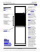
System
Overview
Picture
List
Descriptions
Accessory
Descriptions
Specifications
Physical Size
Information
Related
Documentation
SYSTEM OVERVIEW................................................................................................................................................. 1
TABLE OF CONTENTS ............................................................................................................................................. 4
LIST DESCRIPTIONS ................................................................................................................................................ 5
List Numbers ........................................................................................................................................................ 5
List 1: Common Equipment (Relay Rack or Rail Mounted System) ............................................................... 5
List 2: Common Equipment (Ship Loose System) .......................................................................................... 5
List 10: Main Rectifier Module Mounting Shelf Interface Components ........................................................... 5
List 11: Expansion Rectifier Module Mounting Shelf Interface Components .................................................. 6
List 20: Main Rectifier Module Mounting Shelf to Expansion Rectifier Module Mounting Shelf
Interface Components ...................................................................................................................................... 6
List 21: Expansion Rectifier Module Mounting Shelf to Expansion Rectifier Module Mounting Shelf
Interface Components ...................................................................................................................................... 7
ACCESSORY DESCRIPTIONS ................................................................................................................................. 8
ACU+ (Advanced Control Unit Plus) Controller, P/N 1M820DNA ................................................................... 8
Optional Temperature Probes ............................................................................................................................ 8
Optional SM-Temp Temperature Concentrator, P/N 547490 ......................................................................... 10
Rectifiers ............................................................................................................................................................ 10
Rectifier Module, P/N 1R483500E ................................................................................................................. 10
Rectifier Module Mounting Position Blank Cover Panel, P/N 21140440 ...................................................... 10
Relay Racks and Shipping Brackets ............................................................................................................... 11
Transition Plates to Mount Relay Rack on Top of GNB Absolyte IIP Batteries .......................................... 12
Standard Crimp Lugs and Lug Hardware Kits ............................................................................................... 13
Standard Crimp Lug Tables ........................................................................................................................... 13
3/8-16 Lug Hardware Kit, P/N 556277 ........................................................................................................... 13
Customer Cables ............................................................................................................................................... 14
CAN Bus Input Cable, P/N 556430 ................................................................................................................ 14
CAN Bus Output Cable, P/N 556238 ............................................................................................................. 14
Replacement Assemblies ................................................................................................................................. 14
Wiring Illustrations and Notes ......................................................................................................................... 15
Relay Rack Frame Grounding Requirements ................................................................................................ 15
AC Input Branch Circuit Protection and Wire Size Selection ......................................................................... 15
External Alarm, Reference, Monitoring, and Control Connections ................................................................ 15
DC Output Connections ................................................................................................................................. 20
SPECIFICATIONS .................................................................................................................................................... 22
1.1 Environmental Ratings ............................................................................................................................... 22
1.2 Compliance Information ............................................................................................................................. 22
1.3 System Interface Board Ratings ............................................................................................................... 23
1.4 IB2 (ACU+ Interface Board) Ratings ......................................................................................................... 23
PHYSICAL SIZE INFORMATION ............................................................................................................................ 24
Overall Dimensions ........................................................................................................................................... 24
Weights ............................................................................................................................................................... 24
RELATED DOCUMENTATION ................................................................................................................................ 25
REVISION RECORD ................................................................................................................................................ 26