
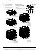
Brochures and Data Sheets

System Application Guide SAG582127100
Spec. No. 582127100 (Model 722NBBB) Issue AA, May 7, 2013
Page 23 of 26
This document is property of Emerson Network Power, Energy Systems, North America, Inc. and contains confidential and proprietary information owned by Emerson Network Power, Energy
Systems, North America, Inc. Any copying, use, or disclosure of it without the written permission of Emerson Network Power, Energy Systems, North America, Inc. is strictly prohibited.
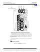
1.3 System Interface Board Ratings
1.3.1 Battery Fuse Alarm Input Rating
(A) The default is 400mV. Anything greater than 400mV causes alarm to be raised.
1.3.2 Load Fuse Alarm Input Signal
(A) Anything greater than 19V causes alarm to be raised.
1.3.3 Battery and Load Shunt Input Rating
(A) 1mV – 150mV.
1.3.4 LVD Sense Input Rating
(A) Normal state is at 60V or less. A RTN signal indicates the contactor is open.
1.3.5 LVD Driver Output Rating
(A) Mono-stable, normal state is 60V or less at 1A continuous rating. Normally closed
contactors are used for mono-stable option.
(B) Bi-Stable, normal state less than 60V and 2A at 500ms – 1000ms pulse rating.
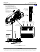
1.4 IB2 (ACU+ Interface Board) Ratings
1.4.1 Digital Input Ratings
(A) Maximum Voltage Rating: 60V DC.
(B) Active High: > 19V DC.
(C) Active Low: < 1V DC.
1.4.2 Relay Ratings
(A) 1A Steady State @ 30V DC.
(B) 3A Peak @ 30V DC.
Home