
Brochures and Data Sheets

SAG582127100 System Application Guide
Issue AA, May 7, 2013 Spec. No. 582127100 (Model 722NBBB)
Page 22 of 26
This document is property of Emerson Network Power, Energy Systems, North America, Inc. and contains confidential and proprietary information owned by Emerson Network Power, Energy
Systems, North America, Inc. Any copying, use, or disclosure of it without the written permission of Emerson Network Power, Energy Systems, North America, Inc. is strictly prohibited.
SPECIFICATIONS
Note: For rectifier module mounting shelf specifications, refer to PD588705000.
For rectifier specifications, refer to Rectifier Instructions (UM1R483500E).
For ACU+ Controller specifications, refer to the ACU+ Controller Instructions (UM1M820BNA).
For ACU+ Controller factory settings, refer to the ACU+ Controller Configuration Drawing (C-drawing).
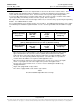
1.1 Environmental Ratings
1.1.1 Operating Ambient Temperature Range: -40°C to +65°C (-40°F to +149°F).
1.1.2 Storage Ambient Temperature Range: -40°C to +85°C (-40°F to +185°F).
1.1.3 Humidity: This Power System is capable of operating in an ambient relative humidity range of
0% to 95%, non-condensing.
1.1.4 Altitude: Capable of operating in an altitude range of -200 feet to 10,000 feet. The maximum
operating ambient temperature should be de-rated by 3°C per 1000 feet above 5000 feet.
1.1.5 Mounting: This product is intended only for installation in a restricted access location on or
above a non-combustible surface.
This product must be located in a controlled environment with access to crafts persons only.
This product is intended for installation in network telecommunication facilities (CO, vault, hut, or
other environmentally controlled electronic equipment enclosure).
This product is intended to be connected to the common bonding network in a network
telecommunication facility (CO, vault, hut, or other environmentally controlled electronic
equipment enclosure).
The DC return connection to this system can remain isolated from system frame and chassis
(DC-I).
This system is suitable for installation as part of the Common Bonding Network (CBN).
Rectifier and rectifier mounting shelf ventilating openings must not be blocked and temperature
of air entering rectifiers must not exceed the rated operating ambient temperature range.
Clearance requirements are:
a) Recommended minimum aisle space clearance for the front of each bay is 2'6".
b) Minimum spacing from the rear of the bay to a wall or other solid surface is that which is
specified for proper rectifier module mounting shelf ventilation. Refer to the rectifier
module mounting shelf Power Data Sheet for ventilation spacing requirements.
Note: Minimum rear spacing specified for ventilation may not permit installation and
maintenance of the system.
Recommended minimum aisle space clearance for the rear of each bay is 2’ 0” to allow
for installation and maintenance.
1.2 Compliance Information
1.2.1 Safety Compliance: This unit meets the requirements of UL 60950-1, Standard for Information
Technology Equipment, and is UL Recognized as a power supply for use in Telephone,
Electronic Data Processing or Information Processing Equipment. This unit meets the
requirements of CAN/CSA 22.2, No. 60950-00 and is tested and Certified by UL ("c UR") as a
Component Type Power Supply.
1.2.2 NEBS Compliance (pending): Compliance verified by a Nationally Recognized Testing
Laboratory (NRTL) per GR-1089-CORE and GR-63-CORE. Contact Emerson Network Power
for NEBS compliance reports.
Rectifier Modules: In order to remain compliant during a fan failure condition, the backup
battery connection must be utilized to provide sufficient power to the loads for up to eight (8)
hours when the system is operated at greater than 50% output power. If no backup battery
connection is used, the system must operate with a redundant module installed.
Home