
Brochures and Data Sheets

System Application Guide SAG582127100
Spec. No. 582127100 (Model 722NBBB) Issue AA, May 7, 2013
Page 21 of 26
This document is property of Emerson Network Power, Energy Systems, North America, Inc. and contains confidential and proprietary information owned by Emerson Network Power, Energy
Systems, North America, Inc. Any copying, use, or disclosure of it without the written permission of Emerson Network Power, Energy Systems, North America, Inc. is strictly prohibited.
Home
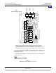
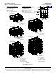
Figure 4
DC Output Connections
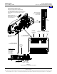
GND RTN
Busbars
-48V DC
Output
Busbars
GND RTN
Busbars
-48V DC
Output
Busbars
GND RTN
Busbars
-48V DC
Output
Busbars
GND RTN
Busbars
-48V DC
Output
Busbars
GND RTN
Busbars
-48V DC
Output
Busbars
Rear
Rear
Rear
Rear
Rear
1-Shelf System
2-Shelf System
3-Shelf System
(1) connection per
two shelves.
(1) connection per
two shelves (top).
(1) connection per
two shelves (bottom).
(1) connection per
two shelves (top).
(1) connection per
single shelf (bottom).
(1) connection per
two shelves (top).
(1) connection per
two shelves (middle).
(1) connection per
single shelf (bottom).
(1) connection per
single shelf.
4-Shelf System
5-Shelf System
-48V DC OUTPUT CONNECTIONS
3/8 Clearance Holes on 1” Centers
(Customer must order or supply
lug mounting hardware.)
Maximum Lug Width:
1.31” for three (3) lugs per polarity.
1.78” for two (2) lugs per polarity.
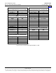
DC Output Connection Options
1. Route cables left, right, or out the back
by repositioning the lug landing busbars
(see UM582127100).
2. Make connections to each shelf
(List 10 and 11).
3. Make connections to every
two (2) shelves (List 20 and 21).