
Brochures and Data Sheets

SAG582127100 System Application Guide
Issue AA, May 7, 2013 Spec. No. 582127100 (Model 722NBBB)
Page 20 of 26
This document is property of Emerson Network Power, Energy Systems, North America, Inc. and contains confidential and proprietary information owned by Emerson Network Power, Energy
Systems, North America, Inc. Any copying, use, or disclosure of it without the written permission of Emerson Network Power, Energy Systems, North America, Inc. is strictly prohibited.
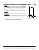
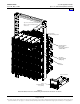
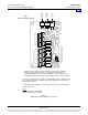
DC Output Connections
DC output leads are connected to the output busbars located on the back of the rectifier shelves. These
busbars provide 3/8” clearance holes for installation of customer-provided two hole lugs that have 1 inch
centers and 3/8 inch bolt clearance holes. Customer must order or provide lug mounting hardware.
You connect DC output leads per a single rectifier shelf in the system or for pairs of rectifier shelves in the
system (depending on how many shelves are in the system). Refer to Figure 4.
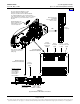
DC output cables can either enter from the right, from the left, or from the rear by repositioning the lug landing
busbars. See UM582127100 for details.
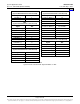
For recommended wire sizes and lug selection, refer to Table 7. For additional lug information, refer to Table
3 and drawings 031110100 through 031110300. See also “3/8-16 Lug Hardware Kit, P/N 556277” on page
13.
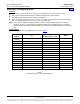
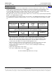
Individual Rectifier Shelf DC Output Connections
4
Ambient Operating
Temperature
Recm 90 C
Wire Size
1
(AWG)
Loop
Length
2
(feet)
Recommended
Crimp Lug
3
40°C
(2) 4/0
87.2
245347400
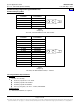
Pair of Rectifier Shelves DC Output Connections
5
[One (1) DC Output Connection per Two (2) Rectifier Shelves]
Ambient Operating
Temperature
Recm 90 C
Wire Size
1
(AWG)
Loop
Length
2
(feet)
Recommended
Crimp Lug
3
40°C
(3) 300 kcmil
185.5
245347600
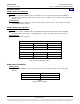
1
Wire sizes based on recommendations of the American National Standards Institute (ANSI)
approved National Fire Protection Association's (NFPA) National Electrical Code (NEC).
Table 310-16 for copper wire at 90°C conductor temperature, operating in ambient of 40°C
was used. For other operating ambient temperatures, refer to the NEC. For operation in
countries where the NEC is not recognized, follow applicable codes.
2
Wire sizes listed are sufficient to restrict voltage drop to 1.0 volt or less for the loop lengths
shown. Loop length is the sum of the lengths of the positive and negative leads.
3
Two-hole lug, 3/8" bolt clearance hole, 1" centers. Refer to drawing 031110100 for lug
crimping information.
4
Single shelf equipped with six (6) rectifiers.
5
Two shelves equipped with a total of twelve (12) rectifiers.
Table 7
Recommended DC Output Wire Sizes and Lugs
Home