
Brochures and Data Sheets

SAG582127100 System Application Guide
Issue AA, May 7, 2013 Spec. No. 582127100 (Model 722NBBB)
Page 18 of 26
This document is property of Emerson Network Power, Energy Systems, North America, Inc. and contains confidential and proprietary information owned by Emerson Network Power, Energy
Systems, North America, Inc. Any copying, use, or disclosure of it without the written permission of Emerson Network Power, Energy Systems, North America, Inc. is strictly prohibited.
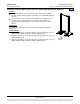
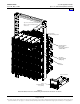
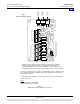
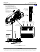
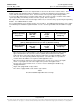
Figure 3
System Interface Boards Connections
A CAN termination plug
must be installed if an
external device or system
is not connected here.
The end of the ACU+ CAN Bus is routed
from the bottom-most rectifier shelf into
the top-most rectifier shelf via cable P/N 556430.
Use cable P/N 556238 to connect external devices
to the end of the ACU+ CAN bus. Access the connector
by removing the top cover from the ACU+ section of
the shelf.
RS-485 Connection
Pin 1: RS485+
Pin 2: RS485-
RS-232 Connection
Pin 1: DCD232
Pin 2: RXD232
Pin 3: TXD232
Pin 4: DTR232
Pin 5: CGND
Pin 7: RTS232
RS-232 RS-485
SYSTEM
TEMP
PROBE 1
SYSTEM
TEMP
PROBE 2
1 5
6 9
21
1
2
1
2
1
2
1
2
1
2
STD
ACU+ Section of Main Shelf
(components removed for
clarity only)
Factory
Connected
to TB5
Internal System
Interface Circuit Card
TB5
External System
Interface Circuit Card
LA BA
OPT
Factory
Connected to
DC Bus and
CAN Bus
Factory
Connected
to TB5
See table
on next page.
Factory
Connected
to TB5
Factory
Connected
to TB5
Wire Size Capacity:
30-12 AWG.
Recommended Torque:
4.4 to 5.3 in-lbs.
Home