
Brochures and Data Sheets

System Application Guide SAG582127100
Spec. No. 582127100 (Model 722NBBB) Issue AA, May 7, 2013
Page 17 of 26
This document is property of Emerson Network Power, Energy Systems, North America, Inc. and contains confidential and proprietary information owned by Emerson Network Power, Energy
Systems, North America, Inc. Any copying, use, or disclosure of it without the written permission of Emerson Network Power, Energy Systems, North America, Inc. is strictly prohibited.
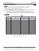
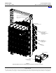
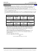
Figure 2
IB2 (ACU+ Interface Board) Connections
IB2
(ACU+ Interface Board)
Switch settings must be in this position
to interface with the ACU+ Controller
-
J12
*
RELAY
SW1
7
J2
J11
5 3
1
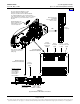
Relay Output Terminal Blocks
Digital Input Terminal Blocks
J9 J8 J7
J6
J5 J4 J3
8 6 4
2
8 7 6 5 4 3
2 1
+
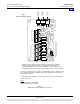
IB2 Board (Top View)
NO
C
NC
NO C NC
NO
C
NC
NO C NC
NO
C
NC
NO C NC
NO
C
NC
NO C NC
5
3
1
46 2
5 3 1
46 2
5
3
1
46 2
5 3 1
46 2
5
3
1
46 2
5
3
1
46 2
5 3 1
46 2
Connector
to ACU+
IB2 TEMP
PROBRE 1
IB2 TEMP
PROBE 2
* The ACU+ relay assigned to “Critical Summary” alarm (relay 1 by default)
will operate in the “Fail Safe Mode”. “Fail Safe Mode” means Relay 1 is
de-energized during an alarm condition, opening the contacts between the
C and NO terminals, and closing the contacts between the C and NC terminals.
The ACU+’s remaining seven (7) relays energize during an alarm condition, closing
the contacts between the C and NO terminals, and opening the contacts between
the C and NC terminals.
Not all I/O points are available for customer connection (some are used for factory
system connections).
J3-J9:
Wire Size Capacity: 16-26 AWG.
Recommended Torque: 2.2 in-lbs.
Home