
Brochures and Data Sheets

System Application Guide SAG582127100
Spec. No. 582127100 (Model 722NBBB) Issue AA, May 7, 2013
Page 15 of 26
This document is property of Emerson Network Power, Energy Systems, North America, Inc. and contains confidential and proprietary information owned by Emerson Network Power, Energy
Systems, North America, Inc. Any copying, use, or disclosure of it without the written permission of Emerson Network Power, Energy Systems, North America, Inc. is strictly prohibited.
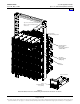
Wiring Illustrations and Notes
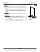
Relay Rack Frame Grounding Requirements
For relay rack grounding requirements, refer to the current edition of the American National Standards
Institute (ANSI) approved National Fire Protection Association's (NFPA) National Electrical Code (NEC),
applicable local codes, and your specific site requirements.
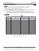
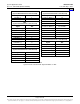
A customer's grounding network lead can be attached to the top of each relay rack. Provision is made for
installing a lead with a two-hole lug that has 1/4" bolt clearance holes on 5/8" centers. Refer to Table 2 for lug
selection.
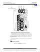
AC Input Branch Circuit Protection and Wire Size Selection
AC input connections are made to the rear of the rectifier module mounting shelf(s). Refer to Power Data
Sheet PD588705000 for connection details.
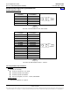
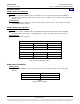
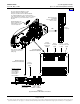
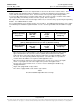
External Alarm, Reference, Monitoring, and Control Connections
Recommended wire size is 22 AWG for loop lengths up to 200 ft. and 18-20 AWG for loop lengths over 200 ft.
Refer to Figure 1, Figure 2, Figure 3, and Table 6.
Home