
Brochures and Data Sheets

SAG582127100 System Application Guide
Issue AA, May 7, 2013 Spec. No. 582127100 (Model 722NBBB)
Page 14 of 26
This document is property of Emerson Network Power, Energy Systems, North America, Inc. and contains confidential and proprietary information owned by Emerson Network Power, Energy
Systems, North America, Inc. Any copying, use, or disclosure of it without the written permission of Emerson Network Power, Energy Systems, North America, Inc. is strictly prohibited.
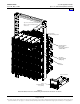
Customer Cables
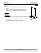
CAN Bus Input Cable, P/N 556430
Features
Provides a 26” ACU+ CAN Bus cable. This cable is used to extend the end of the ACU+ CAN Bus
located in the bottom-most rectifier shelf up into the top most rectifier shelf. See Table 4 for cable pinouts
and wire colors.
Ordering Notes
1) This cable is factory provided for relay rack or rail mounted systems (List 1). For a replacement cable
order P/N 556430, as required.
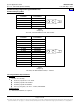
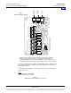
CAN Bus Output Cable, P/N 556238
Features
Provides a 10’ ACU+ CAN Bus cable. This cable is used to extend the end of the ACU+ CAN Bus
outside the main rectifier shelf to other equipment. See Table 4 for cable pinouts and wire colors.
Ordering Notes
1) Order P/N 556238, as required.
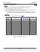
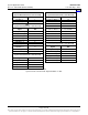
P/N 556430 (Int. CAN)
Signal
Wire Color
TB5
CAN-H
Black
CANx-1
CAN-L
Red
CANx-2
P/N 556238 (Ext. CAN)
Signal
Wire Color
TB5
CAN-H
Black
CANx-1
CAN-L
Red
CANx-2
Table 4
ACU+ Controller CAN Bus Cables
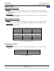
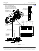
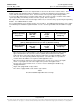
Replacement Assemblies
Ordering Notes
1) Refer to the following table. Refer to the separate rectifier descriptions in this section for their part
numbers.
Item
Part Number
ACU+ Controller
1M820DNA
ACU+ IB2 Interface Board
MA4C5U31
Table 5
Replacement Assemblies
Home