
Brochures and Data Sheets


2013.102
eSure™ Converter C48/24-1500
EmersonNetworkPower.com/EnergySystems (North America)
EmersonNetworkPower.eu/EnergySystems (EMEA)
© Emerson Network Power Energy Systems North America 2013.
Business-Critical Continuity
™
, Emerson Network Power
™
, the Emerson Network Power logo, Emerson
®
and Consider it Solved are service marks and trademarks of Emerson Electric Co.
EnergyMaster
™
, eSure
™
, NetPerform
™
, NetReach
™
, NetSpan
™
, NetSure
®
and NetXtend
™
are trademarks of Emerson Network Power Energy Systems North America.
Technical Specifications
DC Input
Input Voltage, Nominal 48 VDC
Input Voltage, Permitted Variation 41VDC to 58.5VDC
Max Input Current 39.5A
DC Output
Output Voltage, Adjustment Range 24 t o 2 8 VDC
Output Power 1500W@Vout >24VDC
Output Power,
Derated for Input Voltage
See diagram
Output Current 63A
Output Current Limit Set Point 6.3 to 63A
>95%ycneiciff E
Psophometric Noise (system) <2 mV; output noise<38dBrnc
Temperature Derating See diagram
Control and Monitoring
Visual Indications
Green LED: Normal Operation
Yellow LED: Alarm
Red LED: Failure
Flashing Red LED: Fan Failure
Environmental
Temperature Range, Operating -40 to
+80°C, -40 to +176°F
Temperature Range, Storage -40 to +85°C, -40 to +185°F
Relative Humidity 0 to 95%
rewop lluf ta tf 0656 ,m 0002edutitlA
EMC
ETSI EN 300 386 class A, FCC CFR 47 Part 15 class A,
Telcordia GR-1089-CORE class A
05906 LU ,05906 NE ,05906 CEIytefaS
Mechanics
Dimensions (H x W x D)
sbl94.2/gk31.1thgie W
42x 8 4.5x252.5mm/1.65x3.33x9.94 inches
Other Parts
Controller Units See separate ACU/ACU+ and SCU/SCU+ datasheets
Ordering Information
Model Number Description
1C48241500
Converter 48VDC/24VDC 1500W
Diagrams
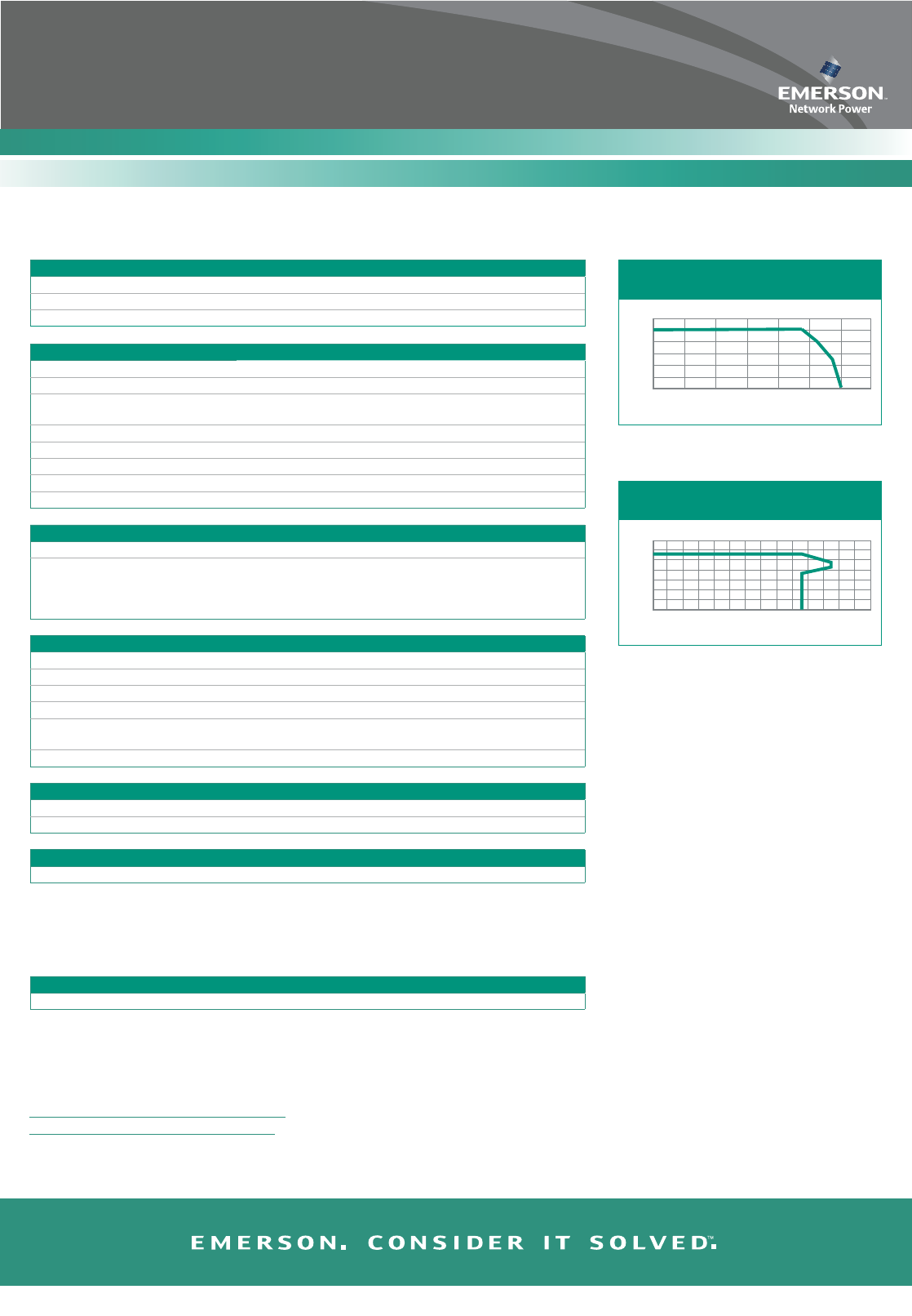
120
100
80
60
40
20
0
-40 -20 0 20 40 60 80 100
Temperature (C°)
% of max output power
Output Power vs. Temperature
35
30
25
20
15
10
5
0
0 10 15 20 25 30 35 40 45 50 55 60 65 70 75
Output Current (A)
Output Voltage (V)
Output voltage vs. Output current
at max. output power 1500 W
Converter Alarm and Signaling Alarm and status reported via CAN bus to system controller