Monitoring For Business-Critical Continuity Liebert OpenComms™ EM User Manual
TABLE OF CONTENTS 1.0 INTRODUCTION . . . . . . . . . . . . . . . . . . . . . . . . . . . . . . . . . . . . . . . . . . . . . . . . . . . . . . . . . .1 1.1 Overview . . . . . . . . . . . . . . . . . . . . . . . . . . . . . . . . . . . . . . . . . . . . . . . . . . . . . . . . . . . . . . . . . . . 2 1.1.1 Dimensions and Mounting Overview - EM & EM PDU Controllers . . . . . . . . . . . . . . . . . . . . . 2 1.1.2 Dimensions and Mounting Overview - vEM-14 Controllers . . . . . . . . . . . . . . . . . .
5.0 GETTING STARTED WITH THE WEB INTERFACE . . . . . . . . . . . . . . . . . . . . . . . . . . . . . . . . . 16 5.1 Open the Web Interface and Log In . . . . . . . . . . . . . . . . . . . . . . . . . . . . . . . . . . . . . . . . . . . . 16 5.2 View Summary Data . . . . . . . . . . . . . . . . . . . . . . . . . . . . . . . . . . . . . . . . . . . . . . . . . . . . . . . . 17 5.3 Sensors Window . . . . . . . . . . . . . . . . . . . . . . . . . . . . . . . . . . . . . . . . . . . . . . . . . . . . . .
FIGURES Figure 1 Figure 2 Figure 3 Figure 4 Figure 5 Figure 6 Figure 7 Figure 8 Figure 9 Front view (EM PDU & vEM-14 controllers shown). . . . . . . . . . . . . . . . . . . . . . . . . . . . . . . . . . . . . 2 Rear view . . . . . . . . . . . . . . . . . . . . . . . . . . . . . . . . . . . . . . . . . . . . . . . . . . . . . . . . . . . . . . . . . . . . . . . 3 Indicators on front of unit. . . . . . . . . . . . . . . . . . . . . . . . . . . . . . . . . . . . . . . . . . . . . . . . . . . . . . . . . .
iv
Introduction 1.0 INTRODUCTION The Liebert OpenComms™ EM is a compact, half-duplex device designed to monitor temperature, humidity, water detection and contact closure and notify personnel when those conditions exceed user-defined limits. The OpenComms EM is available in several models, which vary in size and number and types of ports.
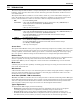
Introduction 1.1 Overview The OpenComms EM features indicator lights on the front, as shown in Figure 1. Figure 1 Front view (EM PDU & vEM-14 controllers shown) EM PDU CONTROLLER Power Link Serial Serial Modem Sensor Sensor 1 2 1 2 A - Power and port indicators (see Table 1) vEM-14 CONTROLLER 1.1.1 Dimensions and Mounting Overview - EM & EM PDU Controllers • The unit is 4.75" wide, x 2.5" deep x 1.625" high (120.7 x 63.5 x 41.3mm).
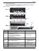
Introduction 1.1.3 Connectors on Back of Unit The back of the OpenComms EM, shown in Figure 2, has an input power source, sensor ports, a modem port and an Ethernet port. The EM PDU and vEM-14 controllers have serial ports, and vEM-14 controllers also have 10 dry contact inputs.
Introduction 1.2 Indicators The front of the OpenComms EM has indicators that show input power to the unit and the status of various connections, as shown in Figure 3 and described in Table 2.
Installation 2.0 INSTALLATION This section provides instructions for installing, mounting and connecting power and other cables to the OpenComms EM. 2.1 Installation Considerations The OpenComms EM must be installed indoors where electrical service is available. The unit should be placed where it can be easily accessed for connecting the unit to a modem, a computer or a network hub and, if used, serial devices.
Installation 2.2 Decide on Placement of the OpenComms EM The unit may either be placed on a level surface or mounted on a wall, depending on the user’s application and the location of equipment to be connected and monitored. vEM-14 controllers may also be mounted in a rack. • If placing the unit on a level surface, such as a shelf or a desk, proceed to 2.3 - Make Connections. • For wall or rack mounting, see the appropriate section for your model: • 2.2.
Installation 2.2.2 Mounting the Unit on a Wall or in a Rack (vEM-14 Controllers) The vEM-14 controller may be mounted on a wall or in a rack, such as the Liebert Foundation. The unit has four holes on each side, as shown in Figure 5. Figure 5 Mounting - vEM-14 Controllers REAR OF UNIT FRONT OF UNIT Holes for rear mounting Holes for front mounting Mounting brackets After determining where to place the unit, check to ensure that you have all the hardware required to install the unit in a rack.
Installation 2.3 Make Connections All ports are on the back of the OpenComms EM. The port placement and port labels differ for each model. Refer to Figure 2 for your model. 2.3.1 Connect Power to the Unit • Connect the DC power adapter to the DCN/Power port on the back of the OpenComms EM, as shown in Figure 2. When power is connected, the Power indicator on the front is ON (red). 2.3.
Assign an IP Address 3.0 ASSIGN AN IP ADDRESS After connecting the OpenComms EM device to your network, the next step is to identify the device to the network by assigning an IP address. Consult Your Network Administrator Consult your network administrator to obtain an IP address that is appropriate for your network, as well as a subnet mask and default gateway address.
Assign an IP Address 3.2 Use ARP to Assign an IP Address This method may be preferable if you are not using a Microsoft host. NOTE These steps must be done on the same network segment where the OpenComms EM is connected. To use the ARP command: 1. Open a command prompt. In Windows, one way to do this is: • Click on the Start button, then on Run. • In the Run window, enter cmd in the Open box, then click OK. 2.
Web Interface Overview 4.0 WEB INTERFACE OVERVIEW This section provides a quick look at the OpenComms EM Web interface and the viewing and configuration functions accessible through tabs at the top of the window. For step-by-step instructions on using the Web interface, proceed to 5.0 - Getting Started With the Web Interface. 4.1 Main Parts of the Web Interface The Web interface gives you access to all the features of the OpenComms EM device. You may use any Internet browser to access the Web interface.
Web Interface Overview 4.2 Tabs The tabs at the top right of the Web interface window provide access to all the functions of the OpenComms EM device. Table 5 summarizes these functions and where to find more information. Table 5 Tab Summary Sensors Power (EM PDU & vEM-14 controllers) Alerts Security Sys Info 4.
Web Interface Overview 4.4 Thresholds in the Web Interface The OpenComms EM collects data from connected sensors at regular intervals. When a reading crosses a user-defined threshold: • The sensor’s status changes. • Alerts are sent—if the unit is configured for e-mail, pager or SNMP trap alerts. 4.4.1 Temperature/Humidity Sensor Thresholds Temperature and humidity sensors have four thresholds: High Critical, High Warning, Low Warning and Low Critical. The Normal range is determined by these limits.
Web Interface Overview 4.4.3 MP Advanced Power Strip Thresholds When using the OpenComms EM to monitor MP Advanced Power Strips, you may set thresholds that will trigger alerts for power, voltage, current and temperature sensors in each power strip. Each sensor has four thresholds: High Critical, High Warning, Low Warning and Low Critical. The Normal range is determined by these limits. Table 9 shows examples of limits for these types of sensors.
Web Interface Overview 4.5 Sensor Names and Status The Web interface displays four items about sensors in all windows available through the Summary, Sensors and Power tabs, as shown in Table 10. The sensor’s Name is an optional user-defined description; the Description is created at the factory and cannot be changed. The Status and Current Value reflect the most recent sensor reading and are color-coded for easy identification. Status is determined by the thresholds that may be configured by the user.
Getting Started With the Web Interface 5.0 GETTING STARTED WITH THE WEB INTERFACE Once the unit is properly installed, you can view its Web interface using an Internet browser. This section provides step-by-step instructions on how to open the Web interface, log in, view monitoring data and view or change configuration settings for the OpenComms EM. 5.1 Open the Web Interface and Log In You must log in each time you open the Web interface.
Getting Started With the Web Interface 5.2 View Summary Data The Summary window provides a quick look at the current status of all connected devices, as shown below. This window also has a Log Out button to exit the Web interface. To access the Summary window, log in (see 5.1 - Open the Web Interface and Log In) and: • Click on the Summary tab at the top of the Web interface. This window also appears after you log in to the Web interface.
Getting Started With the Web Interface 5.3 Sensors Window The Sensors tab provides access to sensor-related data and settings, including: • Setting thresholds that will trigger alerts for each sensor (see 5.3.1 - Configure Sensors) • Creating display names for any sensor (see 5.3.2 - Create or Change Sensor Names) • Viewing graphs of sensor readings and thresholds (see 5.3.3 - View Sensor Graphs) 5.3.
Getting Started With the Web Interface 5.3.2 Create or Change Sensor Names The Sensor Names feature allows you to create a name to help identify a sensor. This name is displayed throughout the Web interface and in notifications sent by pager or e-mail. To access the Sensor Names window, log in (see 5.1 - Open the Web Interface and Log In) and: • Click on the Sensors tab at the top of the Web interface, as shown below.
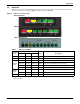
Getting Started With the Web Interface 5.3.3 View Sensor Graphs The OpenComms EM sensor data may be viewed in graphic format, along with the sensor’s upper and lower alarm limits, as described in 5.3.1 - Configure Sensors. The OpenComms EM stores up to 1,440 data samples for each sensor. Sensor data samples can be stored at intervals of 1 minute, 5 minutes, 10 minutes or 15 minutes. (To change the data sample rate, see 5.7.3 - Data Presentation.
Getting Started With the Web Interface Figure 6 Sensor graph - humidity sensor example SENSOR GRAPH Humidity sensor example All button Limit button Graph of upper limits Legend Graph of sensor data Graph of lower limits Refresh button Refresh button The line graph shows the selected sensor’s readings (black) chronologically from left to right—the most current reading is on the far right—as well as Warning (yellow) and Critical (red) limits.
Getting Started With the Web Interface 5.4 Power Window (EM PDU & vEM-14 Controllers) The Power tab provides access to MP Advanced Power Strips connected to the OpenComms EM, including: • • • • 5.4.1 Turning receptacles on or off—all at once, individually or in pairs (see 5.4.1 - Control Receptacles) Setting thresholds that will trigger alerts (see 5.4.2 - Configure Thresholds) Viewing graphs of power strip data (see 5.4.3 - View Power Strip Graphs) Creating display names for any power strip (see 5.4.
Getting Started With the Web Interface Link the Controls of Two Receptacles Two receptacles may be linked for simultaneous control. The receptacles may be on the same power strip or on two different power strips. When two receptacles are linked, the Connections column displays the link as x:y, where x is the OpenComms EM serial port number (1 or 2) and y is the number of the linked receptacle.
Getting Started With the Web Interface 5.4.2 Configure Thresholds You may set thresholds that will trigger alerts for power, voltage, current and temperature sensors in each power strip. Power tab Links to set thresholds Select a power strip To do this: • In the left side of the Power Data window, shown above, select a power strip (Port 1 or 2). • Click on one of the blue links—Power, Voltage, Current or Temperature—in the right side of the window. This opens a configuration window, as shown below.
Getting Started With the Web Interface 5.4.3 View Power Strip Graphs Power strip data may be viewed in graphic format, similar to those of sensor data. To access the Power Strip Graphs window (see 5.4.1 - Control Receptacles for more details): • Click on the Power tab at the top of the Web interface. • Select a port from the left side of the window by clicking on the name of the port. • In the right side of the Power Data window, click on one of the blue links—Power, Voltage, Current or Temperature.
Getting Started With the Web Interface 5.4.4 Create or Change Port Names The Port Names feature allows you to create a name to help identify a serial port. This name is displayed throughout the Web interface and in notifications sent by pager or e-mail. To access the Port Names window, log in (see 5.1 - Open the Web Interface and Log In) and: • Click on the Power tab at the top of the Web interface, as shown below.
Getting Started With the Web Interface 5.5 Alerts Window The OpenComms EM may be configured to send alerts by e-mail or dial pagers to notify personnel when a sensor reading crosses a threshold, either entering a warning or critical state or returning to normal status. See 4.4 - Thresholds in the Web Interface for more information. The Alerts tab provides access to three types of alerts: • E-mail messages (see 5.5.1 - E-Mail Setup) • Pager messages (see 5.5.2 - Modem Setup) • SNMP traps (see 5.5.
Getting Started With the Web Interface 5.5.2 Modem Setup The OpenComms EM may be configured to send a numeric message to a pager. Note: The unit requires an external modem to send pager alerts. The modem port is set at 9600 baud, no parity, 8 data bits and 1 stop bit. For details on connecting the unit to a modem, see 6.1 - Modem Setup and Pinout Guide and 2.3.3 - Connect to a Modem. To generate automatic pager alerts when a sensor reading crosses a threshold, log in (see 5.
Getting Started With the Web Interface 5.5.3 SNMP Trap Alerts Setup The OpenComms EM may be configured to send SNMP trap alerts to a computer whenever the status of a sensor changes from normal to a warning or critical state, as well as a return-to-normal alert when the reading falls within the normal range. These alerts may be sent to up to four IP addresses, typically Network Management Station (NMS). If you activate SNMP traps, see also 5.7.2 - SNMP Information.
Getting Started With the Web Interface 5.6 Security Window To protect configuration settings from unauthorized users, the Web interface allows you to set up users with different levels of access. • A user with Administration privileges has full access, including creating and modifying other user accounts. • Users with Read/Write access may change their own password, but are not permitted to make any other modifications. 5.6.
Getting Started With the Web Interface 5.6.2 Create a New User Account (Administrators Only) An administrator may create user accounts for up to 50 users, including the administrator account. Only users with administrative privileges may create user accounts. To do this, log in as an administrator (see 5.1 - Open the Web Interface and Log In) and: • Click on the Security tab to display the Security window, as shown below.
Getting Started With the Web Interface 5.6.3 Modify an Existing Account (Administrators Only) Users with administrative privileges may change all options on all users’ accounts, including their own. Users without administrative access are prevented from changing anything except their own password; for details, see 5.6.4 - Change Password (Users with Read/Write access). To change a user account, log in as an administrator (see 5.
Getting Started With the Web Interface 5.6.4 Change Password (Users with Read/Write access) Users with Read or Read & Write access may change their password but no other user account information for their own accounts or those of other users. To change your own password, log in (see 5.1 - Open the Web Interface and Log In) and: • Click on the Security tab to display the Security window, as shown below. Security tab Enter & confirm password • Enter a password for this user in the Password box.
Getting Started With the Web Interface 5.7 Sys Info Window The OpenComms EM may be configured to send alerts by e-mail or dial pagers to notify personnel when a sensor reading crosses a threshold, either entering a warning or critical state or returning to normal status. See 4.4 - Thresholds in the Web Interface for more information. The Sys Info tab provides access to system configuration settings: • • • • 5.7.1 Configure your network (see 5.7.1 - Network Connectivity) Change SNMP trap settings (see 5.
Getting Started With the Web Interface 5.7.2 SNMP Information To access the SNMP Information window, log in (see 5.1 - Open the Web Interface and Log In) and: • Click on the Sys Info tab at the top of the Web interface, as shown below. Sys Info tab System information MIB boxes SNMP Information link • Click on the SNMP Information link on the left side of the window. The right side of the window displays setup information for SNMP traps, as shown above.
Getting Started With the Web Interface 5.7.3 Data Presentation To access the Data Presentation window, log in (see 5.1 - Open the Web Interface and Log In) and: • Click on the Sys Info tab at the top of the Web interface, as shown below. Sys Info tab Data sampling Web page refresh rate Temperature units Data Presentation link • Click on the Data Presentation link on the left side of the window.
Getting Started With the Web Interface 5.7.4 Serial Ports NOTE The Serial Port 1 and 2 windows are reserved. This section shows the default settings, which should NOT be changed. To view the Serial Port 1 and 2 windows, log in (see 5.1 - Open the Web Interface and Log In) and: • Click on the Sys Info tab at the top of the Web interface, as shown below.
Pinout Guides 6.0 PINOUT GUIDES 6.1 Modem Setup and Pinout Guide The OpenComms EM must be connected to a modem to send pager alerts when a sensor reading crosses a user-defined threshold (see 5.5.2 - Modem Setup for more information). The unit is compatible with modems that have DB9 or DB25 serial COM ports. A proper cable must be constructed to allow communication between the unit and the modem.
Downloading Firmware Updates 7.0 DOWNLOADING FIRMWARE UPDATES This section explains how to update the unit’s firmware. ! CAUTION When the firmware is updated, all settings except the network configuration are lost. 1. The first step is to download the upgrade text file. To do this, visit Liebert’s Web site at http://www.liebert.com and go to the OpenComms EM section. Or contact Liebert Monitoring Application Support at 1-800-222-5877.
Specifications 8.0 SPECIFICATIONS Table 16 OpenComms EM specifications Power Requirements Input Output Dimensions W x D x H, in. (mm) Weight Mounting Ambient Operating Environment, °F (°C) EM & EM PDU controller vEM-14 controller 120 VAC, 60 Hz 120 VAC, 60 Hz 9 VDC, 500 mA, unregulated 9 VDC, 500 mA, unregulated 4.75 x 2.5 x 1.625 (120.7 x 63.5 x 41.3) 17 x 5 x 1.75 (431.8 x 127 x 44.5mm) 7 oz. (198g) 2 lb. (0.
Ensuring The High Availability 0f Mission-Critical Data And Applications. Emerson Network Power, the global leader in enabling business-critical continuity, ensures network resiliency and adaptability through a family of technologies—including Liebert power and cooling technologies—that protect and support business-critical systems. Liebert solutions employ an adaptive architecture that responds to changes in criticality, density and capacity.