
User manual

Retrofit Installation
38
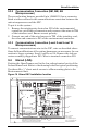
9.3.2 Communication Connection (SM, AM, AG
Microprocessor)
The second wiring harness provided (p/n 159083G1) has a connector
fitted at either end and is the communications connection between the
unit microprocessor and the NIC.
To put it in the system:
1. Remove the existing wire located on P25 of the environmental
controller, cut off the red connector and reconnect the wires to TB2
of the interface card. Ensure correct polarity.
2. Connect one end of the wire harness to TB1 of the interface card;
the other end connects to P25 of the environmental controller.
9.3.3 Communication Connection (Level 0 and Level 10
Microprocessors)
To connect communications wire to the NIC, wire as described above.
Some field modifications of the wiring harnesses are necessary for con-
nection to legacy systems. Level 0 and Level 10: Remove the red con-
nector normally plugged into P25. Wire to terminal connection P25.
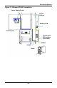
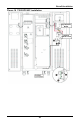
9.4 Himod (LNA)
Position the OpenComms card in the low voltage/control cavity of the
Liebert Himod unit. Refer to the drawing below for typical positioning.
Use three #8 x ½” sheet metal screws to affix mounting plate to the
Environmental unit.
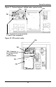
Figure 14 Himod NIC installation location
37C38C37B38B37 3875 76
94
95
96
97 1112
41
42
43
44
45
46
47
48
2450 51 55
56
84 85 82
83
88
89
91 92 93
77
78
NIC
ATTENTION
135655P1
USE
COPPER
CONDUCTORS ONLY
P25
P43
TB3
TB1
110
112
110
Unplug standard P25 Harness and remove
RED connector. Cut and strip wires for installation
to screw connector TB2 on NIC board as shown.
BLACK
RED
RED
BLACK
TB2
Item 111, manual,
to be inserted
in unit installation packet
Item 113, schematic, to be
attached to deadfront
+
-
AM/AG
CONTROL
BOARD
110
Install 2 Harnesses
provided in Item 110 Kit
P43
ONE (OR MORE) ALARM DEVICES HAS BEEN
FACTORY CONNECTED TO THE LOCAL ALARM
INPUT TERMINALS 24 & 50
Unplug standard P43
harnesses from AM/AG
control board and
connect to harness
provided in Item 110 Kit