OpenComms NIC MONITORING USER MANUAL
TABLE OF CONTENTS 1.0 INTRODUCTION . . . . . . . . . . . . . . . . . . . . . . . . . . . . . . . 1 1.1 OpenComms Compatibility . . . . . . . . . . . . . . . . . . . . . . . 2 2.0 INSTALLATION . . . . . . . . . . . . . . . . . . . . . . . . . . . . . . . 5 2.1 2.2 2.3 Retrofit Kit . . . . . . . . . . . . . . . . . . . . . . . . . . . . . . . . . . . . 5 Self-Contained Unit . . . . . . . . . . . . . . . . . . . . . . . . . . . . . 5 User Connections for OpenComms NIC . . . . . . . . . . . . . 6 2.3.
5.4 Modbus Slave Functions . . . . . . . . . . . . . . . . . . . . . . . . 21 5.4.1 5.4.2 5.4.3 5.4.4 5.4.5 5.4.6 5.4.7 5.5 Data Type. . . . . . . . . . . . . . . . . . . . . . . . . . . . . . . . . . . . . . 21 Function Code Support . . . . . . . . . . . . . . . . . . . . . . . . . . . 22 Read/Write Holding Registers (0x03, 0x06, 0x10) . . . . . . 22 Read Input Registers (0x04) . . . . . . . . . . . . . . . . . . . . . . . 22 Read, Set Coil Status (0x01, 0x05, 0x0F) . . . . . . . . . . . . .
9.3 Power Connection (SM, AM, AG Microprocessors). . . . 37 9.3.1 9.3.2 9.3.3 9.4 Power Connection (Level 0 and Level 10 Microprocessors) . . . . . . . . . . . . . . . . . . . . . . . . . . . . . . . . 37 Communication Connection (SM, AM, AG Microprocessor) . . . . . . . . . . . . . . . . . . . . . . . . . . . . . . . . . 38 Communication Connection (Level 0 and Level 10 Microprocessors) . . . . . . . . . . . . . . . . . . . . . . . . . . . . . . . . 38 Himod (LNA) . . . . . . . . . . . . . . . . . . .
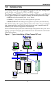
FIGURES Figure 1 Figure 2 Figure 3 Figure 4 Figure 5 Figure 6 Figure 7 Figure 8 Figure 9 Figure 10 Figure 11 Figure 12 Figure 13 Figure 14 Figure 15 Figure 16 Figure 17 Figure 18 Figure 19 Figure 20 Typical installation of OpenComms NIC card . . . . . . . . . . . . . . . 1 Connections . . . . . . . . . . . . . . . . . . . . . . . . . . . . . . . . . . . . . . . . . . 5 Null modem cable diagram . . . . . . . . . . . . . . . . . . . . . . . . . . . . . . 7 NIC main menu in HyperTerminal . . . . . . . . . . .
Introduction 1.0 INTRODUCTION The OpenComms NIC Card transforms Liebert units into manageable nodes within your Network, NMS, and BMS systems. The OpenComms NIC Card contains a standard Ethernet and EIA-485 (2-wire) port designed to support viewing and management through: • HTTP for Web browsers (I.E. 5.
Introduction 1.
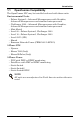
Introduction Table 1 OpenComms availability Factory Option Retrofit Kit Deluxe System 3 and ICS Yes Yes NIC-K-SYS3 Challenger Yes Yes NIC-K-CHALL Unit Retrofit Kit Part # Environmental Products Mini-Mate2 Yes Level 00/05/10/15 Himod Emerson Network Power (CEMS100 / LECS15) 1 NIC-ENCL1 OR 2 Yes NIC Yes Yes NIC Yes 3 Yes 3 Consult sales department Yes Yes 2 37OP000NIC8 Yes Yes 2 4645114G Yes 2 4645114d 3-Phase UPS Npower Hiross 7200 (Italy) Hiross HiPulse (Italy) Yes 3-
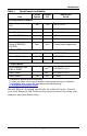
Introduction Table 2 Specifications Electrical Requirements Voltage 18 to 24VAC 50/60 Hz, Single Phase 12 to 36VDC Power 6VA maximum Environmental Conditions, °F (°C) Operating Ambient Temperature 41 to 104 (5 to 40) Storage Ambient Temperature -4 to 140 (-20 to 60) Relative Humidity 10% to 90% RH (Non-condensing) Dimensions, Inches (mm) Unit Only 7 x 4 x 1.5 (178 x 102 x 38) As Shipped 9.75 x 7.0 x 2.5 (248 x 178 x 64) Weight, lb (kg) Unit Only 0.4 (0.2) As Shipped 1.3 (0.
Installation 2.0 INSTALLATION The OpenComms NIC card may be ordered as a factory-installed option, and it may be installed as a kit for field retrofit to existing Liebert units or as a self-contained unit in its own enclosure. If ordered as a factory-installed option, proceed to 2.3 - User Connections for OpenComms NIC. 2.1 Retrofit Kit As a retrofit kit, the circuit board is secured to a metal mounting plate.
Installation 2.3 User Connections for OpenComms NIC The OpenComms NIC can use simultaneous connections, sometimes requiring three user connections: • Permanent network connection • Modbus 485 connection • Temporary serial connection for configuration/setup 2.3.1 Network Port Consult with the network administrator or other responsible party for arranging a network drop to the Liebert equipment. The OpenComms NIC communicates via standard 10 Base-T Ethernet network connection.
Installation Accessing the Configuration Port What you will need: • PC capable of running a terminal emulation application, such as Microsoft Windows® HyperTerminal®. • DB9 Null modem or file transfer cable. (The correct cable will have at a minimum, pins 2 and 3 crossed at the ends.) Null modem cables are commonly found in computers stores and may also be referred to as a file transfer cable.
Installation the Enter key on your keyboard. This will initiate communications with the card and the following screen should be displayed. Figure 4 NIC main menu in HyperTerminal (You can also cycle power on the OpenComms NIC card. This will also initiate communications and provide information on current revision status.) 6. When the message “Initializing Network…” appears, hit the Enter key on your keyboard.
System Configuration 3.0 SYSTEM CONFIGURATION 3.1 DIP Switch Settings A four-position DIP switch is provided, but no user configuration via DIP switches is necessary at this time. 3.2 Service Terminal Refer to Accessing the Configuration Port on page 7 for explicit details on accessing the service terminal / configuration port.
System Configuration Table 3 Service terminal navigation Main Menu 1. System Information 1.1 Name 1.2 Contact 1.3 Location 1.4 Description 2. Network Settings 2.1 Boot / IP Settings 2.1.1 Boot Mode 2.1.1.1 Static 2.1.1.2 BootP 2.1.1.3 DHCP 2.1.2 IP Address 2.1.3 Netmask 2.1.4 Default Gateway 2.2 SNMP Communications 2.2.1 SNMP agent (enable/disable) 2.2.2 Authentication Traps (enable/disable) 2.2.3 Display / Modify Communities 2.2.4 Display / Modify Trap Communities 2.3 Web Server 2.3.
System Configuration System Information Menu The System Information Menu seeks descriptive input to enable the unit to be identified. This data is readable via SNMP queries. The (“) character is not permitted in any of the descriptive fields Network Settings Menu The Network Settings Menu configures network parameters essential for proper network operation. The network administrator or other personnel responsible for the network should be consulted for the proper parameters to be entered in this menu.
System Configuration destination IP address, and the community name for that host. Up to 20 trap communities can be assigned. For Communities and Trap Communities, the information can be entered as a “complex” line — all parameters space-delimited on the command line. Otherwise, the menu items will prompt for each individual parameter. NOTE SNMP v1 communities are transmitted in plain (unencrypted) text across the network.
System Configuration Auxiliary Communications The Auxiliary Communications Menu allows the user to set up the parameters necessary for Modbus communications. The user can enable / disable the Modbus sessions as well as assign the slave ID. Q. will abort all changes. X. will save configuration changes. Once all parameters have been entered, press to return to the Main menu; then press exit and reboot using the new configuration. All parameters are stored in non-volatile flash memory.
Operation 4.0 OPERATION 4.1 SNMP The OpenComms Network Interface Card supports “get,” “getnext,” “set,” “response” and “trap” packets of SNMP (Simple Network Management Protocol). The OpenComms NIC supports MIB-II, RFC1628 and Liebert Global Products MIBs. The terms “alarms” and “conditions” will be used interchangeably through out this description. Alarms are generated and maintained through the RFC 1628 UPS MIB. Conditions are generated and maintained through the Liebert Global Products MIB.
Operation 4.3 RFC 1628 UPS MIB UPS units log alarms in the RFC 1628 UPS MIB. Traps for the UPS units are generated out of the RFC 1628 UPS MIB. There are four traps that may be sent for the UPS units: Trap On Battery, Trap Test Completed, Trap Alarm Entry Added and Trap Alarm Entry Removed. The trap On Battery is sent when the UPS is operating on battery power. This trap will be sent once a minute until the UPS either shuts down or is no longer running on battery power.
Operation [OIDALARMS] 1.3.6.1.2.1.33.1.6.3.1:upsAlarmBatteryBad{} 1.3.6.1.2.1.33.1.6.3.2:upsAlarmOnBattery{} 1.3.6.1.2.1.33.1.6.3.3:upsAlarmLowBattery{} 1.3.6.1.2.1.33.1.6.3.4:upsAlarmDepletedBattery{} 1.3.6.1.2.1.33.1.6.3.5:upsAlarmTempBad{} 1.3.6.1.2.1.33.1.6.3.6:upsAlarmInputBad{} 1.3.6.1.2.1.33.1.6.3.7:upsAlarmOutputBad{} 1.3.6.1.2.1.33.1.6.3.8:upsAlarmOutputOverload{} 1.3.6.1.2.1.33.1.6.3.9:upsAlarmOnByPass{} 1.3.6.1.2.1.33.1.6.3.10:upsAlarmBypassBad{} 1.3.6.1.2.1.33.1.6.3.
Operation 4.4 MIB The Management Information Base (MIB) is a formal document declaring the specifics of the information supported by the SNMP implementation. The administrator for the NMS (or other applications utilizing SNMP to communicate with the Liebert units will need the MIB in order to integrate the Liebert units into the monitoring system. The MIB files are contained on the CD that ships with the product.
Operation 4.8 Diagnostics A number of LEDs are provided on the interface card to provide information for diagnostic purposes.
Modbus Communications and Connectivity 5.0 MODBUS COMMUNICATIONS AND CONNECTIVITY This section describes the Modbus communications protocol as supported by the OpenComms NIC card. It includes information on how to pass information to and from the OpenComms NIC card via Modbus. It is also intended to help facilitate answering questions regarding supported types, frame format, function code support etc. 5.
Modbus Communications and Connectivity 5.3 Physical Connection A Modbus network should consist of one, and only one, host client, and up to 255 slaves uniquely identifiable by their slave ID. The slave ID of each OpenComms NIC is set through the service terminal (configuration) port. (See section 3, System Configuration for more details.) The OpenComms NIC supports multi-drop connection over RS485.
Modbus Communications and Connectivity Figure 7 Exceeding maximum specifications Modbus RTU Master EIA-485 9600,N,8,1 Maximum of 32 devices with combine cable length of 4000 feet R Modbus RTU Master EIA-485 9600,N,8,1 R Maximum of 32 devices with combine cable length of 4000 feet The maximum specification may be exceeded if measures are taken to drive or boost the EIA-485 communication line. Two wire EIA485 repeaters are available through the Liebert Corporation.
Modbus Communications and Connectivity 5.4.2 Function Code Support The OpenComms NIC implements the following Modbus functions. However, integrators will use function code 0x03, and 0x06 most often due to the type of data to be acquired. 0x01 Read Coil Status 0x02 Read Input Status 0x03 Read Holding Registers 0x04 Read Input Registers 0x06 Write Single Holding Register 0x0F Force Multiple Coils 0x10 Preset Multiple Holding Registers 5.4.
Modbus Communications and Connectivity 5.4.6 Read Input Status (0x02) The input status block contains read-only status accessible to the users. It can be read by using function code 0x02 in the same as reading coil status. 5.4.7 Error Handling According to the Modbus specification, the OpenComms NIC composes the following exception responses to the client if an exception or error occurs.
Modbus Communications and Connectivity the OpenComms NIC module primarily uses Function Code 3 (Read Holding Registers) and Function Code 6 (Preset Single Register). Data Field(s) The data field varies in length depending on whether the message is a request or a response to a packet. This field typically contains information required by the slave device to perform the command specified or to pass back data to the master device.
NIC Setup and Testing 6.0 NIC SETUP AND TESTING The NIC has a specific setup that must be in place before the card will function properly. There are jumpers on the board that must be in the correct locations. The positions of these jumpers are numbered on the board itself. A small triangle silk screened on the board represents pin 1 for each set of pins to which jumpers may be applied. 6.1 Jumper Placement J13, J14, and J18 on the board must have jumpers installed on them.
NIC Setup and Testing 6.2 Testing the Network “Ping” is a tool used to test the network. At the command prompt, type, “ping
”. Ping will respond that it received a reply from the card if the card is functioning properly on the network. If the card is not functioning properly or is not connecting to the network, ping will respond that the request it sent to the card has timed out.NIC Setup and Testing Then, select number 2 for Display/Modify Communities. Verify that the IP Addresses listed are valid for your network. Verify that you are typing in the correct community name when trying to access SNMP. The community name is case sensitive. Once this information is verified, reboot the card and try to access SNMP again. 6.
Firmware Updates 7.0 FIRMWARE UPDATES The firmware in the OpenComms NIC card can be updated to take advantage of the latest release of software that may contain feature enhancements, new unit compatibility or service patches. The firmware is updated through the OpenComms NIC cards’ serial port, using a terminal emulation program like HyperTerminal in MS Windows Operating Systems. This procedure has multiple steps and requires that 3 files be downloaded to the OpenComms NIC card.
Firmware Updates 7.2 Establishing Communication—Service Terminal Settings 1. Launch HyperTerminal. Once you see the following screen, select Cancel. 2. Select the disconnect icon from the menu bar . This step ensures that you will be able to modify the configuration settings. 3. Go to File > Properties to make configuration changes. Under the Connect To setting, choose the appropriate communications port for your computer. Generally this is Com 1. 4.
Firmware Updates 7.3 ! Firmware Update Procedure CAUTION The firmware download process is timed. After the firmware download is initiated as described below, the user has approximately 1 minute to finish initialization. Before beginning the download, determine the location of the firmware files so that the download can be completed within the time constraints. 1. After the communication settings are adjusted, press the Enter key on your keyboard.
Firmware Updates 8. When the above prompt is displayed, start the file download process by selecting Transfer – Send File… from the HyperTerminal menu, as shown at right. 9. Select Xmodem for the Protocol and browse to locate the file OCNIC_REVx.x00.0_BLDxxx_FILE1.s19. 10. Click on Send in the dialog box. NOTE Do not press any keys on your keyboard or the firmware download will abort. 11. The screen at right will appear when the download begins.
Firmware Updates Once the last file is downloaded, the screen at right will appear. Repeat Steps 2 through 4 to change the baud rate back to 9600 bps as show in the illustration below right. After the communication settings are adjusted, hit the Enter key on your keyboard. The screen at right will appear. You can also cycle power on the OpenComms NIC card. This action will also initiate communications and provide information on current revision status.
External Enclosures 8.0 EXTERNAL ENCLOSURES 8.1 Power Connection Power for the OpenComms Network card should be sourced from the supplied wall-plug transformer. Use field-supplied wiring to connect the outer terminals on the transformer to the screw connectors at TB3 on the Network Interface card. A field-supplied ground wire attaches to the center terminal on the transformer and connects to the grounding stud in the lower corner of the enclosure.
Retrofit Installation 9.0 RETROFIT INSTALLATION 9.1 Environmental Installation Retrofit kits are designed specifically for individual units. Consult your local Liebert representative for pricing, part numbers and installation help. 9.1.1 Deluxe System/3 Position the OpenComms card in the low voltage/control cavity of the Liebert Deluxe System 3 unit. Refer to Figures 10, 11 and 12 for typical positioning. Use three #8 x 1/2" sheet metal screws to affix mounting plate to the environmental unit.
Retrofit Installation Figure 11 Deluxe System 3 chilled water control cavity TB3 P43 P25 TB1 TB2 - Connects to screw terminals 77 and 78; (see schematic) Figure 12 ICS control cavity TB3 TB1 TB2 - Connects to screw terminals 77 and 78; (see schematic) P43 P25 35
Retrofit Installation Figure 13 Challenger installation location TB1 TB3 TB2 - Connects to screw terminals 77 and 78; (see schematic) P43 P25 Electric Panel The OpenComms Network card mounts on the Challenger’s L-plate.
Retrofit Installation 9.2 System Wiring (SM, AM, AG Microprocessors) Two wiring harnesses are included with the retrofit kit, one for the power connection and the second for communications. They are of sufficient length for use with the Deluxe System/3 and ICS units and the microprocessors listed above. For the Challenger product series, use the longer wiring harnesses included with the NIC-K-Chall kit. NOTE Board illustrations are shown only for location of connections.
Retrofit Installation 9.3.2 Communication Connection (SM, AM, AG Microprocessor) The second wiring harness provided (p/n 159083G1) has a connector fitted at either end and is the communications connection between the unit microprocessor and the NIC. To put it in the system: 1. Remove the existing wire located on P25 of the environmental controller, cut off the red connector and reconnect the wires to TB2 of the interface card. Ensure correct polarity. 2.
Retrofit Installation 9.4.1 System Wiring (Himod) Two wiring harnesses are included with the retrofit kit, one for the power connection and the second for communications. They are of sufficient length for use with the Himod unit. NOTE Board illustrations are shown only for location of connections. Board location and wire length may change depending upon the specific installation. 9.4.
Retrofit Installation 9.6 Emerson Network Power (CEMS100 / LECS15) The kit includes a special cable to allow simple interconnection between the controller and the OpenComms NIC. Questions about the retrofit kits should be directed to the International Sales department. Contact: yc.kok@emersonnetwork.com.au 9.7 UPS Installation Retrofit kits are designed specifically for individual units. Consult your local sales / service representative for pricing, part numbers and installation help. 9.
Retrofit Installation Figure 15 NPower UPS NIC installation Power Supply Board Option Section SiteScan IFM Control Door OpenComms NIC location (see detail) IGMnet 24VAC Detail 41
Retrofit Installation 9.9 7200 UPS Retrofit Kits are designed specifically for individual units. Consult your local sales / service representative for pricing, part numbers and installation help. ! CAUTION Before installing the kit P/N 4645114G for Network Interface Card (P/N 4590063X), in the 7200 Series UPS, it is necessary to power down that unit.
Retrofit Installation Figure 16 7200 UPS NIC installation Logic Operator Board Network Interface Card 43
Retrofit Installation 9.10 HiPulse UPS Retrofit Kits are designed specifically for individual units. Consult your local sales / service representative for pricing, part numbers and installation help. ! CAUTION Before installing the kit P/N 4645114D for Network Interface Card (P/N 4590063X), in the HiPulse UPS, it is necessary to power down that unit.
Retrofit Installation Figure 17 HiPulse installation 45
Retrofit Installation 9.11 Static Switch2 Retrofit kits are designed specifically for individual units. Consult your local sales / service representative for pricing, part numbers and installation help. Figure 18 STS2 typical NIC location RS-232 (DB-9 connector) for setup only.
Retrofit Installation Figure 20 STS2 NIC installation, 100 - 600A units See Option Location Detail REMOTE SOURCE SELECT (OPTION) PROGRAMMABLE RELAY BOARD (OPTION) PROGRAMMABLE RELAY BOARD (OPTION) INPUT CONTACT ISOLATOR BOARD (OPTION) CONTROL WIRING Front View With Front Door Removed 9.12 Option Location Detail NETWORK INTERFACE CARD (NIC) (OPTION) COMMS BOARD FOR SITESCAN, EXTERNAL AND INTERNAL MODEM INTERFACE (OPTION) STS Retrofit kits are designed specifically for individual units.
Retrofit Installation 48
OpenComms NIC The Company Behind the Products With over a million installations around the globe, Liebert is the world leader in computer protection systems.