
Installation manual


20 Sensor Installation: F-Series
Wiring
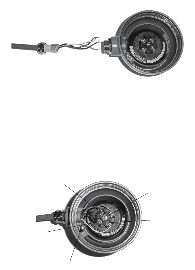
Figure 16 Gland body and core processor housing
5. Insert the wires through the gland body and assemble the gland by tightening the gland nut. If desired,
leave sufficient wire length inside the core processor housing to allow the housing to rotate without
damaging the wires.
6. Identify the wires in the 4-wire cable. The 4-wire cable supplied by Micro Motion consists of one pair
of 18 AWG (0,80 mm
2
) wires (red and black), which should be used for the VDC connection, and one
pair of 22 AWG (0,35 mm
2
) wire (green and white), which should be used for the RS-485 connection.
Connect the four wires to the numbered slots on the core processor (Figure 17).
Figure 17 Connecting the wires at the core processor
7. Reinstall and tighten the core processor housing cover.
8. Additional wiring instructions for the transmitter can be found in the transmitter manual.
Note: Never ground the 4-wire cable shield and shield drain wire(s) at the transmitter.
Core processor housing internal ground screw
• For connections to earth ground (if core processor cannot be grounded via sensor piping
and local codes require ground connections to be made internally)
• Do not connect shield drain wires to this terminal
Terminal 1
Power supply + (Red wire)
Terminal 2
Power supply – (Black wire)
Terminal 3
RS-485A (White wire)
Terminal 4
RS-485B (Green wire)