
Installation manual


Sensor Installation: F-Series 15
Mounting the Sensor
Step 3 Mounting the Sensor
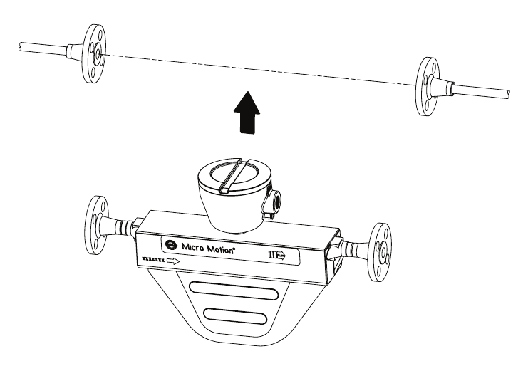
Use your common practices to minimize torque and bending load on process connections. Figure 10 illustrates
how to mount the sensor. To reduce the risk of condensation or excessive moisture, the conduit opening
should not point upward (if possible). The conduit opening of the junction box or core processor can be
rotated freely to facilitate wiring.
Figure 10 Mounting an F-Series sensor
Mounting Model F300A electronics
The electronics of a Model F300A sensor are mounted at the end of a flexible conduit. In addition to
mounting the sensor housing in the pipeline as shown in Figure 10, the Model F300A electronics need to be
mounted to a wall or instrument pole (see Figure 11). A mounting bracket is shipped with the sensor for use in
securing the electronics to a wall or instrument pole.
To mount the electronics:
1. Use four 5/16″ (8 mm) bolts or two 5/16″ (8 mm) U-bolts to mount the bracket to a wall or
instrument pole.
2. Slide the core processor, junction box, or Model 1700/2700 transmitter into the bracket groove.
3. Secure the electronics to the bracket with the four #10 screws provided.