POWER AVAILABILITY 2U Hardwire POD™ USER MANUAL Power Output Distribution 120 Volt
TABLE OF CONTENTS IMPORTANT SAFETY INSTRUCTIONS . . . . . . . . . . . . . . . . . . . . . 1 GLOSSARY OF SYMBOLS . . . . . . . . . . . . . . . . . . . . . . . . . . . . 3 INTRODUCTION AND SYSTEM DESCRIPTION . . . . . . . . . . . . . . . 4 System Description . . . . . . . . . . . . . . . . . . . . . . . . . . . . . . . . . . . 4 RACK MOUNT INSTALLATION. . . . . . . . . . . . . . . . . . . . . . . . . . 5 INSTALLATION ON GXT 2U UPS. . . . . . . . . . . . . . . . . . . . . . . 6 HARDWIRE CONNECTIONS. . . . . .
FIGURES Figure 1 Figure 2 Figure 3 Figure 4 Figure 5 Figure 6 Figure 7 Figure 8 UPS mode of operation . . . . . . . . . . . . . . . . . . . . . . . . . . . . 4 Utility/maintenance bypass mode . . . . . . . . . . . . . . . . . . . 4 2U Hardwire POD with rack mounting brackets . . . . . . . 5 Attaching POD securing brackets to rear of UPS . . . . . . . 6 Conduit entry. . . . . . . . . . . . . . . . . . . . . . . . . . . . . . . . . . . . 7 Removing wiring access doors . . . . . . . . . . . . . . . . . . . .
IMPORTANT SAFETY INSTRUCTIONS SAVE THESE INSTRUCTIONS ! WARNING Do not attempt to service this product yourself. Opening or removing the cover may expose you to dangerous voltages, even when the AC cord is disconnected from the electrical receptacle. Refer all servicing to qualified service personnel. This manual contains important instructions that should be followed during installation and operation of the 2U Hardwire POD™.
! ! ! CAUTION This device receives power from multiple sources. Before servicing this device, remove all connections and cut power from the utility branch input. Before servicing the UPS, follow “Maintenance of UPS” instructions in the user manual for your UPS. CAUTION This device is for use in a clean, temperature-controlled, indoor environment that is free of conductive contaminants. Route power supply cords so they are not walked on or pinched in any way.
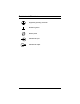
GLOSSARY OF SYMBOLS Equipment grounding conductor Bonded to ground Electric phase Indicates AC input Indicates AC output 3
INTRODUCTION AND SYSTEM DESCRIPTION Congratulations on your choice of the Liebert 2U Hardwire POD™. The 2U Hardwire POD provides maintenance bypass capability as well as power output distribution. The Liebert 2U Hardwire POD can be used on UPS in the rack mount or tower configuration. The Liebert 2U Hardwire POD provides an isolated path of power for your UPS system for preventive maintenance or service.
RACK MOUNT INSTALLATION 1. Rack mount installation of the 2U POD is possible with the use of the rack mounting brackets (shipped with the POD). See Figure 3. 2. The rack mount brackets allow you to rack mount the POD in a 19" enclosure (23" to 19" rack adapters are available as options from Liebert if you are using 23" Foundation or equivalent cabinet). 3. The POD can be mounted to face one of four directions depending on your application, and utilizing the rack mount brackets provided. 4.
INSTALLATION ON GXT 2U UPS NOTE This manual provides instructions for the 2U POD only. Refer to your UPS manual for UPS operation and installation instructions. 1. Unpack the 2U POD carefully, noting the packing method. Retain the box and packing material for possible future shipments. 2. Visually inspect the 2U POD for freight damage. Report damage to the carrier and your local dealer or Liebert representative. 3.
HARDWIRE CONNECTIONS Electrical Installation Considerations ! ! ! CAUTION This UPS must be installed by competent electrical personnel and wired in accordance with local/national electrical codes. CAUTION The utility input supply to the POD must be protected by a branch rated circuit breaker. The UPS output must also be protected with a circuit breaker connected to the load, rated to carry the input current, and be capable of breaking the maximum expected short circuit current of this branch circuit.
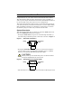
Wiring access doors on each end of the POD allow access to the wiring compartments by opening the top and rear of the POD. Each access door is retained using two Phillips head screws. The center screw and center panel should not be removed. Figure 6 Removing wiring access doors REAR VIEW CAUTION - RISK OF ELECTRIC SHOCK, SO NOT REMOVE COVER. NO USER SERVICEABLE PARTS INSIDE. REFER SERVICING TO QUALIFIED SERVICE PERSONNEL.
Wiring Instructions 1. Remove the wiring access doors by removing the two Phillips head screws that secure them. 2. Determine which of the two available conduit entry points are to be used. Knock out the conduit entry hole for the location and size of conduit to be used. 3. Connect conduit bushing and conduit and run utility load wiring. Inspect wiring to ensure it is not pinched. Make connections to the terminal blocks as labeled. The wiring terminals are labeled. 4.
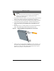
APPLY FEED POWER 1. Next attach the POD to the securing brackets (see Figure 7). The POD can be installed to face one of three different directions utilizing the same mounting procedures. Select the direction of mounting to accommodate the conduit entry connections. Figure 7 Attaching POD to securing brackets 2. Make sure the 2U POD rotary switch is in the UTILITY position. Close the branch circuit breaker providing UTILITY input power. ! WARNING The 2U POD is now electrically live.
START EQUIPMENT 1. Turn on all loads hardwired to the output of the POD. The 2U POD now powers your equipment in the UTILITY mode. 2. Turn ON the loads and ensure all are up and operating properly. 3. Start the UPS according to its specific user manual. 4. Verify that the UPS lamp (green) on the 2U POD is illuminated. If so, transfer the rotary switch from UTILITY to UPS. The load is now being supplied with conditioned power through the UPS. 5.
INDICATOR LAMPS Utility This amber lamp is illuminated when utility power is present. It signals that you may transfer the loads to maintenance bypass (UTILITY mode) operation via the rotary switch. During a utility power outage, this light will be off and the UPS will supply battery back-up power to the connected loads if in UPS position. UPS Available This green lamp is illuminated when there is output power available from the UPS.
OPERATION Transfer to Maintenance Bypass To transfer to maintenance bypass (UTILITY) from UPS, follow the following steps: 1. Ensure the Utility lamp (amber lamp) is illuminated. If the lamp is not illuminated, refer to the Troubleshooting section. 2. Transfer the rotary switch from UPS to UTILITY. 3. Turn the UPS off. 4. Disconnect the two cables connecting the UPS to the 2U Hardwire POD. 5. You may now service/remove the UPS.
TROUBLESHOOTING Problem Cause Solution UTILITY not present. Call qualified service personnel to restore power. Utility Branch Circuit Breaker may be open. Verify that the branch circuit breaker is closed. 2U Hardwire POD input power not connected to UTILITY. Refer to 2U Hardwire POD installation instructions in this manual: • Installation on GXT 2U UPS and • Rack Mount Installation. UPS output power not present. Turn on UPS. Refer to UPS user manual.
SPECIFICATIONS Transfer Time (to and from maintenance bypass) < 6 milliseconds Operating Ambient Temperature 32°F to 104°F (0°C to +40°C) Storage Ambient Temperature -4°F to 140°F (-20°C to +60°C) Dimensions with brackets W x D x H: in. (mm) 3.5 x 3.0 x 15.5 (88.0 x 77.0 x 394.
16
POWER AVAILABILITY 2U Hardwire POD™ USER MANUAL The Company Behind the Products Technical Support/Service With over a million installations around the globe, Liebert is the world leader in computer protection systems.