POWER AVAILABILITY 2U POD™ USER MANUAL Power Output Distribution 120 Volt
TABLE OF CONTENTS IMPORTANT SAFETY INSTRUCTIONS . . . . . . . . . . . . . . . . . . . . . . . . . . . . . . . . . . . . . . . . . . 1 GLOSSARY OF SYMBOLS . . . . . . . . . . . . . . . . . . . . . . . . . . . . . . . . . . . . . . . . . . . . . . . . . . 2 INTRODUCTION AND SYSTEM DESCRIPTION . . . . . . . . . . . . . . . . . . . . . . . . . . . . . . . . . . . . . 3 System Description . . . . . . . . . . . . . . . . . . . . . . . . . . . . . . . . . . . . . . . . . . . . . . . . . . . . . . .
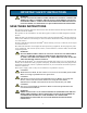
IMPORTANT SAFETY INSTRUCTIONS ! WARNING DO NOT ATTEMPT TO SERVICE THIS PRODUCT YOURSELF. OPENING OR REMOVING THE COVER MAY EXPOSE YOU TO DANGEROUS VOLTAGES, EVEN WHEN THE AC CORD IS DISCONNECTED FROM THE ELECTRICAL OUTLET. REFER ALL SERVICING TO QUALIFIED SERVICE PERSONNEL. SAVE THESE INSTRUCTIONS This manual contains important instructions that should be followed during installation and operation of the 2U POD™. This product is not intended for use with life support or other U.S.
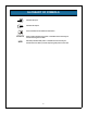
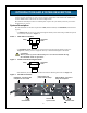
GLOSSARY OF SYMBOLS • Indicates AC Input. Indicates AC Output. i Consult the manual for additional information. UTILITY UTILITY lamp indicates local power is available and the load may be transferred to bypass the UPS. UPS UPS lamp indicates UPS power is available and the load may be transferred to the UPS to provide computer-grade power to the load.
INTRODUCTION AND SYSTEM DESCRIPTION Congratulations on your choice of the Liebert 2U POD™. The Liebert 2U POD provides maintenance bypass capability as well as power output distribution. The Liebert 2U POD can be used on UPSs in the rack mount or tower configuration. The Liebert 2U POD provides an isolated path of power for your UPS system for preventive maintenance or service. System Description The 2U POD has two modes of operation: UPS (UPS available) and UTILITY (maintenance bypass).
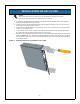
INSTALLATION ON GXT 2U UPS NOTE This manual provides instructions for the 2U POD only. Refer to your UPS manual for UPS operation and installation instructions. 1. Unpack the 2U POD carefully, noting the packing method. Retain the box and packing material for possible future shipments. 2. Visually inspect the 2U POD for freight damage. Report damage to the carrier and your local dealer or Liebert representative. 3.
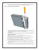
6. Next attach the POD to the securing brackets (see Figure 5). The POD can be installed to face one of three different directions utilizing the same mounting procedures. Figure 5 Attaching POD to securing brackets 7. Make sure the 2U POD rotary switch is in the UTILITY position. Plug the 2U POD input cord (labeled “UTILITY”) into the utility outlet (wall receptacle). WARNING: The 2U POD is now electrically live. The UTILITY lamp (orange) should now be illuminated. 8.
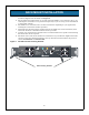
RACK MOUNT INSTALLATION 1. Rack mount installation of the 2U POD is possible with the use of the rack mounting brackets (shipped with the POD). See Figure 6. 2. The rack mount brackets allow you to rack mount the POD in a 19" enclosure (23" to 19" rack adapters would have to be purchased separately if you are using our 23" Foundation or equivalent cabinet). 3. The POD can be mounted to face one of four directions depending on your application, utilizing the rack mount brackets provided. 4.
INDICATOR LAMPS UTILITY Indicator Lamp This orange lamp is illuminated when utility power is present (see Figure 7). It signals that you may transfer the loads to maintenance bypass (UTILITY mode) operation via the rotary switch. During a utility power outage, this lamp will be off and the UPS will supply battery back-up power to the connected loads. UPS Indicator Lamp This green lamp is illuminated when there is output power available from the UPS (see Figure 7).
OPERATION Transfer to Maintenance Bypass To transfer to maintenance bypass (utility) from UPS, use the following steps: 1. Ensure the UTILITY lamp (orange) is illuminated. If the lamp is not illuminated, refer to Troubleshooting section. 2. Transfer the rotary switch from UPS to UTILITY, provided the UTILITY lamp is illuminated on the 2U POD. 3. Turn the UPS off. 4. Disconnect the two cables connecting the UPS to the 2U POD. 5. You may now service the UPS.
SPECIFICATIONS Transfer Time (to and from maintenance bypass) < 6 milliseconds Operating Ambient Temperature 32°F to 104°F (0°C to +40°C) Storage Ambient Temperature -4°F to 140°F (-20°C to +60°C) Dimensions W x D x H: in. (mm) 3.5 x 3.0 x 15.5 (88 x 77 x 394) Weight: lbs (kg) 10 (4.5) Length of input utility cord: ft (m) 10 (3.0) Length of input cord going to UPS: ft (m) 6 (1.
TROUBLESHOOTING Problem UTILITY lamp (orange) not illuminated. Cause Solution Utility not present. Call qualified service personnel to restore power to receptacle. 2U POD input cord not connected to utility. Refer to 2U POD installation instructions in this manual: • Installation on GXT 2U UPS and • Rack Mount Installation. UPS output power not present. Turn on UPS. Refer to UPS user manual. UPS input and/or output cord not connected to 2U POD.
POWER AVAILABILITY 2U POD™ USER MANUAL The Company Behind the Products Technical Support With over a million installations around the globe, Liebert is the world leader in computer protection systems. Since its founding in 1965, Liebert has developed a complete range of support and protection systems for sensitive electronics: United States 1050 Dearborn Drive P.O.