
Technical Specifications

Modbus RTU and Modbus TCP Protocols - UPS Systems
211 Liebert
®
IntelliSlot
®
Modbus/BACnet
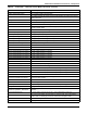
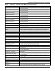
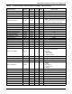
System Output Power The sum total power of all system output phases
System Output RMS Current Phs A The system output RMS current for Phase A
System Output RMS Current Phs B The system output RMS current for Phase B
System Output RMS Current Phs C The system output RMS current for Phase C
System Output Voltage RMS A-B The system output RMS voltage between phases A and B
System Output Voltage RMS A-N The system output RMS voltage between phases A and Neutral
System Output Voltage RMS B-C The system output RMS voltage between phases B and C
System Output Voltage RMS B-N The system output RMS voltage between phases B and Neutral
System Output Voltage RMS C-A The system output RMS voltage between phases C and A
System Output Voltage RMS C-N The system output RMS voltage between phases C and Neutral
System Redundant UPS Modules Number of redundant UPS modules in the system
System Shutdown - EPO System shutdown due to Emergency Power Off (EPO)
System Shutdown - REPO System shutdown due to Remote Emergency Power Off (REPO)
System Status The operating status for the system
System UPS Module Count Number of UPS modules in the system
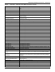
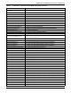
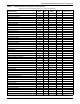
The main battery disconnect status. Main Battery Disconnect Status
Time Remaining - ECO Mode Time remaining before current active ECO Mode session stops.
Total System Operating Time The cumulative operation time of the unit
Trap Filter Disconnect Trap filter disconnect
Unexpected Main Battery Disconnect
Closure
The main battery disconnect has closed unexpectedly.
UPS Battery Status UPS battery status
UPS Module Type UPS module type
UPS Output on Bypass The output power is supplied by the bypass
UPS Output Source UPS output source
UPS System Output Source The UPS system's output power source
Vdc Backfeed The voltage between battery and DC bus measurements is out of tolerance.
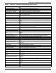
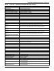
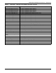
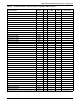
Table 64 Liebert NXL
™
- 50Hz, CE version (Models 48 and 49) - Glossary
Data Label Data Description