
Technical Specifications

Modbus RTU and Modbus TCP Protocols - UPS Systems
209 Liebert
®
IntelliSlot
®
Modbus/BACnet
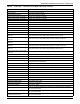
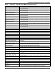
Program Input Contact 04
When the signal from [Program Input Contact 04] is active the function assigned to
this contact is executed.
Program Input Contact 05
When the signal from [Program Input Contact 05] is active the function assigned to
this contact is executed.
Program Input Contact 06
When the signal from [Program Input Contact 06] is active the function assigned to
this contact is executed.
Program Input Contact 07
When the signal from [Program Input Contact 07] is active the function assigned to
this contact is executed.
Program Input Contact 08
When the signal from [Program Input Contact 08] is active the function assigned to
this contact is executed.
Program Input Contact 09
When the signal from [Program Input Contact 09] is active the function assigned to
this contact is executed.
Program Input Contact 10
When the signal from [Program Input Contact 10] is active the function assigned to
this contact is executed.
Program Input Contact 11
When the signal from [Program Input Contact 11] is active the function assigned to
this contact is executed.
Program Input Contact 12
When the signal from [Program Input Contact 12] is active the function assigned to
this contact is executed.
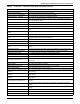
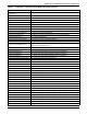
Rectifier Active Filter Rectifier input active filter configuration
Rectifier Configuration Change
Request
This event indicates that the battery is not configured and PFC is not enabled.
Rectifier Failure Rectifier failure - rectifier is off
Rectifier Input Passive Filter Rectifier input passive filter configuration
Rectifier Passive Filter Switch Rectifier input passive filter switch configuration
Rectifier Pulse Count Rectifier pulse count per cycle configuration
Rectifier Status rectifier status
Regeneration Active Regeneration operation is active.
Regeneration Operation Failure
Regeneration operation has been terminated due to bypass source instability or unit
misoperation.
Regeneration Operation Terminated Regeneration operation is not active.
Restart Delay - ECO Mode
The time delay that the conditions to activate ECO Mode must be satisfied before
ECO Mode can be reactivated during an active session.
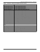
SCC Event Summary Summary of any active user alarms or faults on the SCC
Schedule Action - ECO Mode
This setting gives the user the ability to choose the action of a schedule entry to be
either stop or start.
Schedule Day of Week - ECO Mode
This setting represents the day of the week when an associated ECO Mode schedule
entry action will take effect.
Schedule Hour - ECO Mode
This setting represents the hour of the day when an associated schedule entry action
will take effect.
Schedule Minute - ECO Mode
This setting represents the minute of the hour when an associated schedule entry
action will take effect.
Schedule Operation State - ECO
Mode
This setting gives the user the ability to either enable or disable a schedule entry if
the action is Start.
Service Code Active Service code is running
Static Bypass Switch Static Bypass Switch state - On/Off
Static Switch Type Static switch type configuration
Sum of MMS Output RMS Currents
for Phase A
The sum of the multi-module system output RMS currents for phase A
Sum of MMS Output RMS Currents
for Phase B
The sum of the multi-module system output RMS currents for phase B
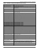
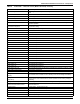
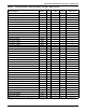
Table 64 Liebert NXL
™
- 50Hz, CE version (Models 48 and 49) - Glossary
Data Label Data Description