
User Manual


Table Of Contents
- Important Safety Instructions
- SAVE THESE INSTRUCTIONS
- 1.0 Introduction
- 2.0 Startup
- 3.0 Operation with iCOM Control
- 4.0 Liebert iCOM Display Components and Functions
- Figure 2 Liebert iCOM display components
- Table 1 Keyboard icons and functions
- Figure 3 Liebert iCOM default screen symbols
- 4.1 Navigating Through the Liebert iCOM Display
- 4.2 Changing Operational Settings
- 4.3 Changing Liebert iCOM’s Display Settings
- 4.4 Graphical Data Record
- 4.5 Liebert iCOM Service Menu Icons and Legend
- 4.6 Wiring for Unit-to-Unit Communications—U2U
- 4.7 Entering Network Setup Information
- 4.8 Viewing Multiple Units with a Networked Large Display
- 5.0 Operation
- 6.0 Alarm Descriptions
- 6.1 Standard Alarms
- 6.1.1 Change Filter
- 6.1.2 Compressor Overload
- 6.1.3 High Head Pressure
- 6.1.4 High Humidity
- 6.1.5 High Humidity and Low Humidity (Simultaneously)
- 6.1.6 High Temperature
- 6.1.7 High Temperature and Low Temperature (Simultaneously)
- 6.1.8 Humidifier Problem
- 6.1.9 Loss of Air Flow
- 6.1.10 Loss of Power
- 6.1.11 Low Humidity
- 6.1.12 Low Suction Pressure
- 6.1.13 Low Temperature
- 6.1.14 Main Fan Overload
- 6.1.15 Short Cycle
- 6.2 Optional Alarms
- 6.3 Set Alarms—User Menus
- 6.1 Standard Alarms
- 7.0 Component Operation and Maintenance
- 7.1 System Testing
- 7.2 Filters
- 7.3 Blower Package
- 7.4 Refrigeration System
- 7.4.1 Suction Pressure
- 7.4.2 Discharge Pressure
- 7.4.3 Superheat
- 7.4.4 Thermostatic Expansion Valve
- 7.4.5 Hot Gas Bypass Valve—Not Available on Digital Scroll Units
- 7.4.6 Air Cooled Condenser
- 7.4.7 Water/Glycol Cooled Condensers
- 7.4.8 Motorized Ball Valve—Digital Scroll Compressor
- 7.4.9 Regulating Valve—Scroll Compressor
- 7.4.10 Drycooler Settings
- 7.4.11 Compressor Oil
- 7.5 Compressor Replacement
- 7.6 Facility Fluid and Piping Maintenance for Water and Glycol Systems
- 7.7 Humidifier
- 8.0 Troubleshooting
- Table 12 Blower troubleshooting
- Table 13 Chilled water troubleshooting
- Table 14 Compressor and refrigeration system troubleshooting
- Table 15 Dehumidification troubleshooting
- Table 16 Glycol pump troubleshooting
- Table 17 Infrared humidifier troubleshooting
- Table 18 Steam generating humidifier troubleshooting
- Table 19 Reheat troubleshooting
- 9.0 Monthly Maintenance Inspection Checklist
- 10.0 Semiannual Maintenance Inspection Checklist
Troubleshooting
60
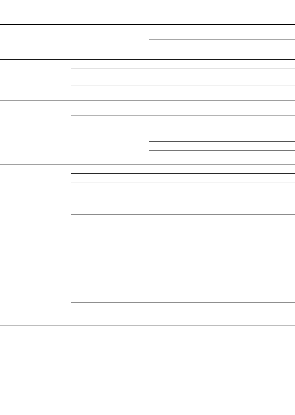
Table 18 Steam generating humidifier troubleshooting
Symptom Possible Cause Check or Remedy
False canister full indication Foaming
Check drain valve to ensure that it drains freely. Check and
replace if defective.
Check water supply. If commercially softened, reconnect to
raw water supply. If connected to hot water reconnect to
cold water.
Main 24 VAC fuse or circuit
breaker trips
Shorts or loose connections Check the wiring connections of the 24 VAC circuit.
Faulty circuit board Replace the circuit board.
Main fuses blow
approximately 15 seconds
after unit is activated
Faulty solenoid Check for magnetic field at coil.
Conductivity too high
Check amp draw of humidifier on startup. If it exceeds rated
amps, increase setting of the % pot on the circuit board
Main fuses blow when
drain valve is activated.
Mineral deposits obstruct
drain valve
Check drain valve for obstructions and clean if necessary.
Faulty solenoid Check for magnetic field at coil.
Faulty circuit board Replace circuit board.
Unit On, humidifier will not
operate
Humidifier not receiving power
Verify that RUN/DRAIN switch is in the RUN position.
Check fuses or CBs and replace or reset if necessary.
Make sure molex connector is securely plugged into circuit
board and that no wires are loose.
Contactor pulled in, but no
water enters canister
No water available to unit Check external shutoff valves.
Clogged fill line strainer Clean or replace fill line strainer.
Wiring breaks or loose
connections
Check for faulty wiring and loose connections.
Faulty circuit board Replace circuit board.
Water enters canister, but
canister full circuit activates
at a low water level
Foaming Check drain valve and water supply.
Canister interface connections
incorrect
Check connection on component plate in humidifier cabinet.
Terminal #1 on the square block interface device must be
connected to L2 of the power terminal block. L2 must also
be connected to the electrode closest to the steam outlet
port.
Verify that the red wire from Terminal #2 on the interface
connects to the red top terminal on the canister. This is the
one farthest from the steam outlet port and is the high water
sensor probe.
Full isolation has broken down
Remove red canister full wire from canister. If normal
operation resumes, canister must be replaced. Remove the
wire from Terminal #3 on the interface. If normal operation
resumes, canister full interface must be replaced.
Drain assembly not operating
freely
Check and replace coil or valve if necessary.
Faulty circuit board Replace circuit board
Canister fills but overflows
Canister full circuit does not
activate
Check wiring of canister full interface. Replace circuit board.