
User Manual


Table Of Contents
- Important Safety Instructions
- SAVE THESE INSTRUCTIONS
- 1.0 Introduction
- 2.0 Startup
- 3.0 Operation with iCOM Control
- 4.0 Liebert iCOM Display Components and Functions
- Figure 2 Liebert iCOM display components
- Table 1 Keyboard icons and functions
- Figure 3 Liebert iCOM default screen symbols
- 4.1 Navigating Through the Liebert iCOM Display
- 4.2 Changing Operational Settings
- 4.3 Changing Liebert iCOM’s Display Settings
- 4.4 Graphical Data Record
- 4.5 Liebert iCOM Service Menu Icons and Legend
- 4.6 Wiring for Unit-to-Unit Communications—U2U
- 4.7 Entering Network Setup Information
- 4.8 Viewing Multiple Units with a Networked Large Display
- 5.0 Operation
- 6.0 Alarm Descriptions
- 6.1 Standard Alarms
- 6.1.1 Change Filter
- 6.1.2 Compressor Overload
- 6.1.3 High Head Pressure
- 6.1.4 High Humidity
- 6.1.5 High Humidity and Low Humidity (Simultaneously)
- 6.1.6 High Temperature
- 6.1.7 High Temperature and Low Temperature (Simultaneously)
- 6.1.8 Humidifier Problem
- 6.1.9 Loss of Air Flow
- 6.1.10 Loss of Power
- 6.1.11 Low Humidity
- 6.1.12 Low Suction Pressure
- 6.1.13 Low Temperature
- 6.1.14 Main Fan Overload
- 6.1.15 Short Cycle
- 6.2 Optional Alarms
- 6.3 Set Alarms—User Menus
- 6.1 Standard Alarms
- 7.0 Component Operation and Maintenance
- 7.1 System Testing
- 7.2 Filters
- 7.3 Blower Package
- 7.4 Refrigeration System
- 7.4.1 Suction Pressure
- 7.4.2 Discharge Pressure
- 7.4.3 Superheat
- 7.4.4 Thermostatic Expansion Valve
- 7.4.5 Hot Gas Bypass Valve—Not Available on Digital Scroll Units
- 7.4.6 Air Cooled Condenser
- 7.4.7 Water/Glycol Cooled Condensers
- 7.4.8 Motorized Ball Valve—Digital Scroll Compressor
- 7.4.9 Regulating Valve—Scroll Compressor
- 7.4.10 Drycooler Settings
- 7.4.11 Compressor Oil
- 7.5 Compressor Replacement
- 7.6 Facility Fluid and Piping Maintenance for Water and Glycol Systems
- 7.7 Humidifier
- 8.0 Troubleshooting
- Table 12 Blower troubleshooting
- Table 13 Chilled water troubleshooting
- Table 14 Compressor and refrigeration system troubleshooting
- Table 15 Dehumidification troubleshooting
- Table 16 Glycol pump troubleshooting
- Table 17 Infrared humidifier troubleshooting
- Table 18 Steam generating humidifier troubleshooting
- Table 19 Reheat troubleshooting
- 9.0 Monthly Maintenance Inspection Checklist
- 10.0 Semiannual Maintenance Inspection Checklist
Component Operation and Maintenance
52
Autoflush Controls
Use the LCD display, menu, and keys on the front control panel to program the autoflush controls.
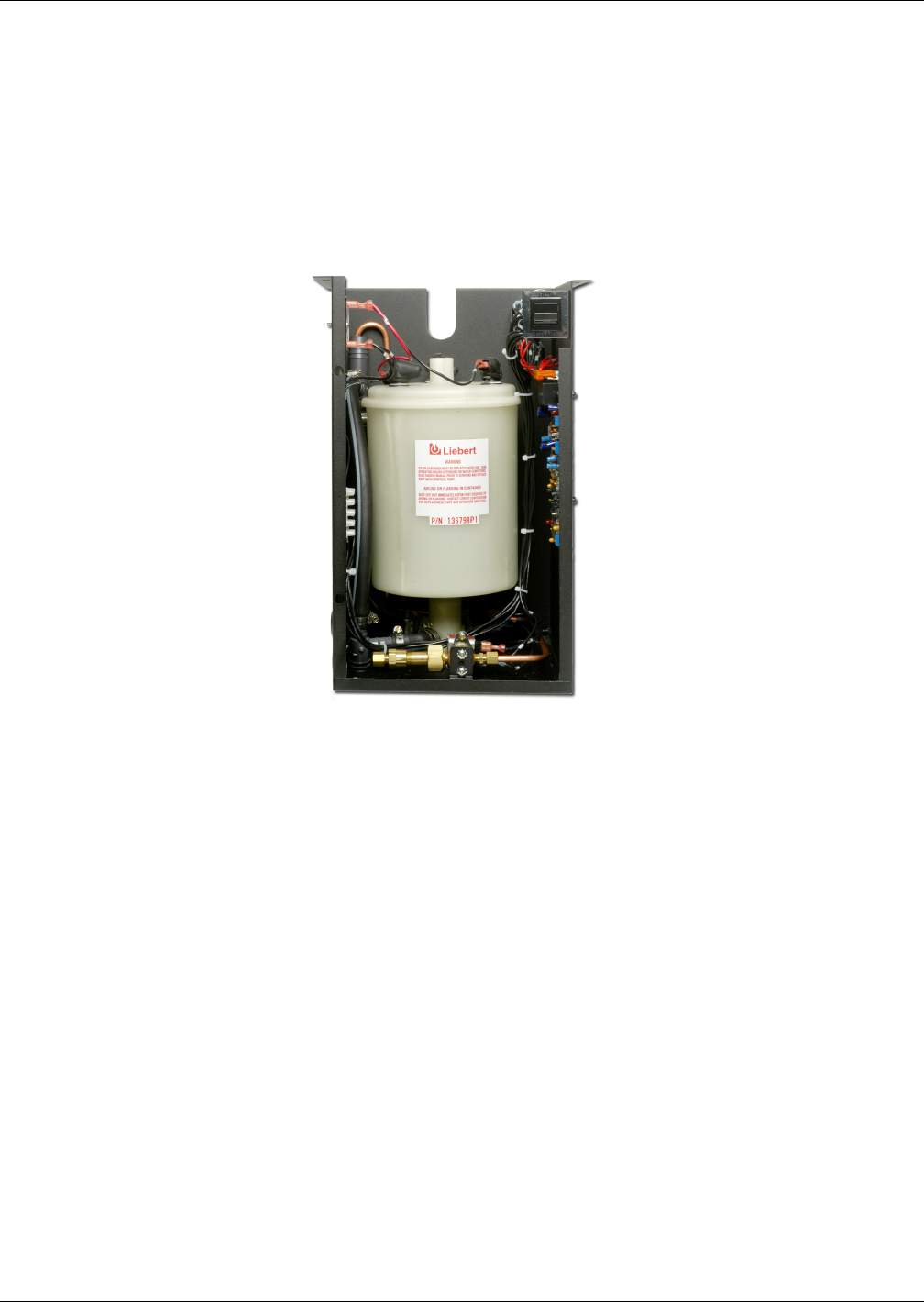
7.7.2 Steam Generating Humidifier
Steam generating humidifiers are designed to operate in voltage ranges from 200 to 575 volts and
generate 11 pounds (5 kg) of steam per hour. These humidifiers operate efficiently over a wide range
of water quality conditions and automatically adjust to changes in the conductivity of water. The
humidifiers drain and refill to maintain an amperage setpoint and alert the operator when the
humidifier canister needs to be replaced. The humidifier is in the lower section of upflow units; it is in
the middle section of downflow units.
Figure 27 Steam generating humidifier