
User Manual


Table Of Contents
- Important Safety Instructions
- SAVE THESE INSTRUCTIONS
- 1.0 Introduction
- 2.0 Startup
- 3.0 Operation with iCOM Control
- 4.0 Liebert iCOM Display Components and Functions
- Figure 2 Liebert iCOM display components
- Table 1 Keyboard icons and functions
- Figure 3 Liebert iCOM default screen symbols
- 4.1 Navigating Through the Liebert iCOM Display
- 4.2 Changing Operational Settings
- 4.3 Changing Liebert iCOM’s Display Settings
- 4.4 Graphical Data Record
- 4.5 Liebert iCOM Service Menu Icons and Legend
- 4.6 Wiring for Unit-to-Unit Communications—U2U
- 4.7 Entering Network Setup Information
- 4.8 Viewing Multiple Units with a Networked Large Display
- 5.0 Operation
- 6.0 Alarm Descriptions
- 6.1 Standard Alarms
- 6.1.1 Change Filter
- 6.1.2 Compressor Overload
- 6.1.3 High Head Pressure
- 6.1.4 High Humidity
- 6.1.5 High Humidity and Low Humidity (Simultaneously)
- 6.1.6 High Temperature
- 6.1.7 High Temperature and Low Temperature (Simultaneously)
- 6.1.8 Humidifier Problem
- 6.1.9 Loss of Air Flow
- 6.1.10 Loss of Power
- 6.1.11 Low Humidity
- 6.1.12 Low Suction Pressure
- 6.1.13 Low Temperature
- 6.1.14 Main Fan Overload
- 6.1.15 Short Cycle
- 6.2 Optional Alarms
- 6.3 Set Alarms—User Menus
- 6.1 Standard Alarms
- 7.0 Component Operation and Maintenance
- 7.1 System Testing
- 7.2 Filters
- 7.3 Blower Package
- 7.4 Refrigeration System
- 7.4.1 Suction Pressure
- 7.4.2 Discharge Pressure
- 7.4.3 Superheat
- 7.4.4 Thermostatic Expansion Valve
- 7.4.5 Hot Gas Bypass Valve—Not Available on Digital Scroll Units
- 7.4.6 Air Cooled Condenser
- 7.4.7 Water/Glycol Cooled Condensers
- 7.4.8 Motorized Ball Valve—Digital Scroll Compressor
- 7.4.9 Regulating Valve—Scroll Compressor
- 7.4.10 Drycooler Settings
- 7.4.11 Compressor Oil
- 7.5 Compressor Replacement
- 7.6 Facility Fluid and Piping Maintenance for Water and Glycol Systems
- 7.7 Humidifier
- 8.0 Troubleshooting
- Table 12 Blower troubleshooting
- Table 13 Chilled water troubleshooting
- Table 14 Compressor and refrigeration system troubleshooting
- Table 15 Dehumidification troubleshooting
- Table 16 Glycol pump troubleshooting
- Table 17 Infrared humidifier troubleshooting
- Table 18 Steam generating humidifier troubleshooting
- Table 19 Reheat troubleshooting
- 9.0 Monthly Maintenance Inspection Checklist
- 10.0 Semiannual Maintenance Inspection Checklist
Component Operation and Maintenance
51
Changing Humidifier Lamps
1. Open disconnect switch.
2. Open front panel.
3. Remove screws securing line voltage compartment cover, then remove the cover.
4. In line voltage compartment, disconnect one end of the purple jumpers, then locate the burned out
bulb with a continuity meter.
5. Remove humidifier pan. Refer to Removing the Pan on page 50.
6. Remove lamp brackets (2) under lamps.
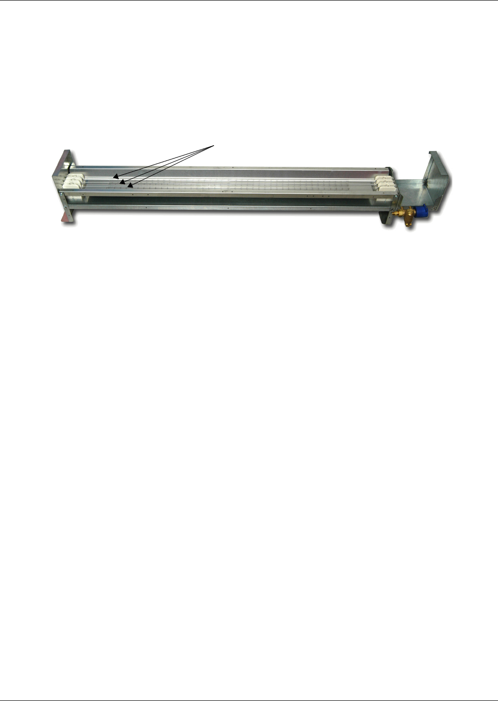
Figure 26 Infrared humidifier lamps
7. Loosen two screws securing bulb wires to junction block.
8. Pull bulb straight down.
9. Replace bulb. Wrap wires once loosely around bulb. This will support the bulb and also allow for
thermal expansion. Make sure lamp wires are secure in the junction block.
NOTICE
Risk of oily deposits. Can shorten component life.
Do not touch the quartz lamps with your bare hands. Oily deposits such as fingerprints will
severely shorten bulb life. Use clean cotton gloves at all times.
10. Reverse Steps 1 through 6 to reassemble.
Autoflush Infrared Humidifier Cleaning System
NOTICE
Risk of improper water pressure. Can cause improper component operation.
To operate properly, the Autoflush Humidifier requires a water source that can deliver at
least 1 gpm (0.063 l/s) with a minimum pressure of 20 psig (138 kPa).
The autoflush system will periodically flush the humidifier pan with water to prevent the buildup of
water minerals due to saturation. Because water conditions vary, the amount of water flushing
through the system may be programmed to match local needs.
Water amounts between 110% and 500% of the amount needed for humidification may be selected.
Operation of the flushing system is then automatic and no further adjustments need to be made.
Autoflush Operation
The operation of the autoflush is divided into four steps, beginning with a call for humidification.
1. If the humidifier has not been activated for over 30 hours, the autoflush will flow water into the
pan for about 30 seconds. This will provide a minimum amount of water in the pan and prevent
heat damage to the humidifier pan. Humidifier lamps are Off.
2. If the humidifier has been activated within the last 30 hours, Step 1 is bypassed. The autoflush
will flow water into the pan for about 4 minutes. The humidifier lamps are On and the humidifier
is operational during this period. When the pan is filled (the fill cycle has timed out), the water
make-up valve is closed.
3. The water make-up valve remains Off and the humidifier lamps are On for a maximum of
9-1/2 minutes.
4. After the 9-1/2 minute delay, the autoflush adds water to the pan to replenish the water used in
humidification and flush the pan of mineral solids. This amount of water is adjustable from 110%
to 500% in increments of 10%. At the end of this cycle, the make-up valve is closed. Steps 3 and 4
repeat as long as humidification is required.
Humidifier Lamps