
User Manual


Table Of Contents
- Important Safety Instructions
- SAVE THESE INSTRUCTIONS
- 1.0 Introduction
- 2.0 Startup
- 3.0 Operation with iCOM Control
- 4.0 Liebert iCOM Display Components and Functions
- Figure 2 Liebert iCOM display components
- Table 1 Keyboard icons and functions
- Figure 3 Liebert iCOM default screen symbols
- 4.1 Navigating Through the Liebert iCOM Display
- 4.2 Changing Operational Settings
- 4.3 Changing Liebert iCOM’s Display Settings
- 4.4 Graphical Data Record
- 4.5 Liebert iCOM Service Menu Icons and Legend
- 4.6 Wiring for Unit-to-Unit Communications—U2U
- 4.7 Entering Network Setup Information
- 4.8 Viewing Multiple Units with a Networked Large Display
- 5.0 Operation
- 6.0 Alarm Descriptions
- 6.1 Standard Alarms
- 6.1.1 Change Filter
- 6.1.2 Compressor Overload
- 6.1.3 High Head Pressure
- 6.1.4 High Humidity
- 6.1.5 High Humidity and Low Humidity (Simultaneously)
- 6.1.6 High Temperature
- 6.1.7 High Temperature and Low Temperature (Simultaneously)
- 6.1.8 Humidifier Problem
- 6.1.9 Loss of Air Flow
- 6.1.10 Loss of Power
- 6.1.11 Low Humidity
- 6.1.12 Low Suction Pressure
- 6.1.13 Low Temperature
- 6.1.14 Main Fan Overload
- 6.1.15 Short Cycle
- 6.2 Optional Alarms
- 6.3 Set Alarms—User Menus
- 6.1 Standard Alarms
- 7.0 Component Operation and Maintenance
- 7.1 System Testing
- 7.2 Filters
- 7.3 Blower Package
- 7.4 Refrigeration System
- 7.4.1 Suction Pressure
- 7.4.2 Discharge Pressure
- 7.4.3 Superheat
- 7.4.4 Thermostatic Expansion Valve
- 7.4.5 Hot Gas Bypass Valve—Not Available on Digital Scroll Units
- 7.4.6 Air Cooled Condenser
- 7.4.7 Water/Glycol Cooled Condensers
- 7.4.8 Motorized Ball Valve—Digital Scroll Compressor
- 7.4.9 Regulating Valve—Scroll Compressor
- 7.4.10 Drycooler Settings
- 7.4.11 Compressor Oil
- 7.5 Compressor Replacement
- 7.6 Facility Fluid and Piping Maintenance for Water and Glycol Systems
- 7.7 Humidifier
- 8.0 Troubleshooting
- Table 12 Blower troubleshooting
- Table 13 Chilled water troubleshooting
- Table 14 Compressor and refrigeration system troubleshooting
- Table 15 Dehumidification troubleshooting
- Table 16 Glycol pump troubleshooting
- Table 17 Infrared humidifier troubleshooting
- Table 18 Steam generating humidifier troubleshooting
- Table 19 Reheat troubleshooting
- 9.0 Monthly Maintenance Inspection Checklist
- 10.0 Semiannual Maintenance Inspection Checklist
Component Operation and Maintenance
46
Manual Flushing—The valve may be flushed by rotating the socket head screw clockwise. This
screw must be in the OUT position (counterclockwise) for normal valve operation.
Valve Disassembly
1. Shut off the water supply by using isolating valves.
2. Relieve the tension on the main spring by turning the adjusting screw (or collar) as far as it will
go (provide a container to catch water below the valve).
3. Remove four screws extending through the main spring housing.
4. Remove the center assembly screws for access to all internal parts.
5. Clean the seat if possible. If the seat is pitted or damaged, replace the valve rubber disc and valve
seat.
6. After valve is reassembled check for leaks.
7. Readjust head pressure control.
Testing Function of Valve—When the refrigeration system has been Off for approximately 10 to 15
minutes, the water flow should stop.
If the water continues to flow, the valve is either improperly adjusted (with head pressure too low) or
the pressure sensing capillary is not connected properly to the condenser.
7.4.10 Drycooler Settings
Applications with the Optional Stat Setting require field piping to be insulated to prevent condensa-
tion. Table 8 shows acceptable applications where stats must be adjusted to Optional Setting.
Aquastats must be field-adjusted to Optional Setting for:
• GLYCOOL/Dual Cool applications
• Single Drycooler loops with motor ball valve flow controls (motor ball valves are used on all Lie-
bert Challenger 3000 and ITR units with digital compressors).
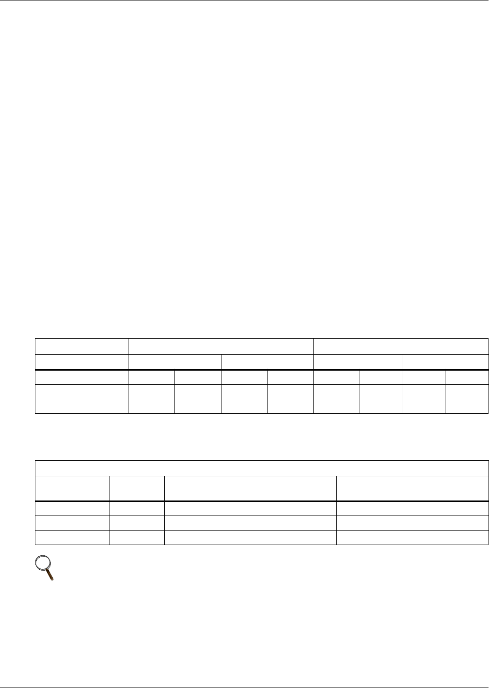
Table 8 Water/glycol system conditions requiring optional settings for aquastats
Cooling Type Glycool Glycol
Flow Control MBV WRV MBV WRV
Drycoolers in Loop 1 Multiple 1 Multiple 1 Multiple 1 Multiple
Stat Setting
1
Optional Optional Optional Optional Optional Factory Factory Factory
Insulate Field Piping Yes Yes Yes Yes Yes No No No
1. See Table 9.
2. MBV=motor ball valve; WRV=water regulating valve
Table 9 Aquastat settings—two-fan through four-fan drycoolers
Dial Setting (Stat Open Temp) Set for Mid Differential 8°F (4.4°C) Rise to Close
Aquastat # Fans
Factory Setting
(Glycol) (see Notes 1 and 2)
Optional Setting
(GLYCOOL) (see Note 3)
AQ1 F1 65°F (18.3°C) 35°F (1.7°C)
AQ2 F2 & F3 75°F (23.9°C) 45°F (7.2°C)
AQ3 F4 70°F (21.1°C) 40°F (4.4°C)
NOTE
1. All drycoolers are shipped at Factory Setting.
2. Factory Setting is used for all glycol applications, except single drycooler loops with motor
ball valve controls.
3. Stats must be field-adjusted to Optional Setting for GLYCOOL/Dual Cool applications
and all single drycooler loops using motor ball valve flow controls.