
User Manual


Table Of Contents
- Important Safety Instructions
- SAVE THESE INSTRUCTIONS
- 1.0 Introduction
- 2.0 Startup
- 3.0 Operation with iCOM Control
- 4.0 Liebert iCOM Display Components and Functions
- Figure 2 Liebert iCOM display components
- Table 1 Keyboard icons and functions
- Figure 3 Liebert iCOM default screen symbols
- 4.1 Navigating Through the Liebert iCOM Display
- 4.2 Changing Operational Settings
- 4.3 Changing Liebert iCOM’s Display Settings
- 4.4 Graphical Data Record
- 4.5 Liebert iCOM Service Menu Icons and Legend
- 4.6 Wiring for Unit-to-Unit Communications—U2U
- 4.7 Entering Network Setup Information
- 4.8 Viewing Multiple Units with a Networked Large Display
- 5.0 Operation
- 6.0 Alarm Descriptions
- 6.1 Standard Alarms
- 6.1.1 Change Filter
- 6.1.2 Compressor Overload
- 6.1.3 High Head Pressure
- 6.1.4 High Humidity
- 6.1.5 High Humidity and Low Humidity (Simultaneously)
- 6.1.6 High Temperature
- 6.1.7 High Temperature and Low Temperature (Simultaneously)
- 6.1.8 Humidifier Problem
- 6.1.9 Loss of Air Flow
- 6.1.10 Loss of Power
- 6.1.11 Low Humidity
- 6.1.12 Low Suction Pressure
- 6.1.13 Low Temperature
- 6.1.14 Main Fan Overload
- 6.1.15 Short Cycle
- 6.2 Optional Alarms
- 6.3 Set Alarms—User Menus
- 6.1 Standard Alarms
- 7.0 Component Operation and Maintenance
- 7.1 System Testing
- 7.2 Filters
- 7.3 Blower Package
- 7.4 Refrigeration System
- 7.4.1 Suction Pressure
- 7.4.2 Discharge Pressure
- 7.4.3 Superheat
- 7.4.4 Thermostatic Expansion Valve
- 7.4.5 Hot Gas Bypass Valve—Not Available on Digital Scroll Units
- 7.4.6 Air Cooled Condenser
- 7.4.7 Water/Glycol Cooled Condensers
- 7.4.8 Motorized Ball Valve—Digital Scroll Compressor
- 7.4.9 Regulating Valve—Scroll Compressor
- 7.4.10 Drycooler Settings
- 7.4.11 Compressor Oil
- 7.5 Compressor Replacement
- 7.6 Facility Fluid and Piping Maintenance for Water and Glycol Systems
- 7.7 Humidifier
- 8.0 Troubleshooting
- Table 12 Blower troubleshooting
- Table 13 Chilled water troubleshooting
- Table 14 Compressor and refrigeration system troubleshooting
- Table 15 Dehumidification troubleshooting
- Table 16 Glycol pump troubleshooting
- Table 17 Infrared humidifier troubleshooting
- Table 18 Steam generating humidifier troubleshooting
- Table 19 Reheat troubleshooting
- 9.0 Monthly Maintenance Inspection Checklist
- 10.0 Semiannual Maintenance Inspection Checklist
Component Operation and Maintenance
43
Checking Refrigerant Charge (Lee–Temp/Flood Back Head Pressure Control)
The system refrigerant level must be checked periodically. To do so:
1. Adjust temperature setpoint in the unit so that the compressor will run continuously.
2. The refrigerant level is visible through two sight glasses on the receiver and will vary with
ambient temperature.
a. 40°F (4.4°C) and lower — Midway on the bottom sight glass.
b. 40 to 60°F (4.4 to 15.6°C) — Bottom sight glass should be clear with liquid.
c. 60°F (15.6°C) and above — Midway on the top sight glass.
3. Return temperature setpoint to desired number.
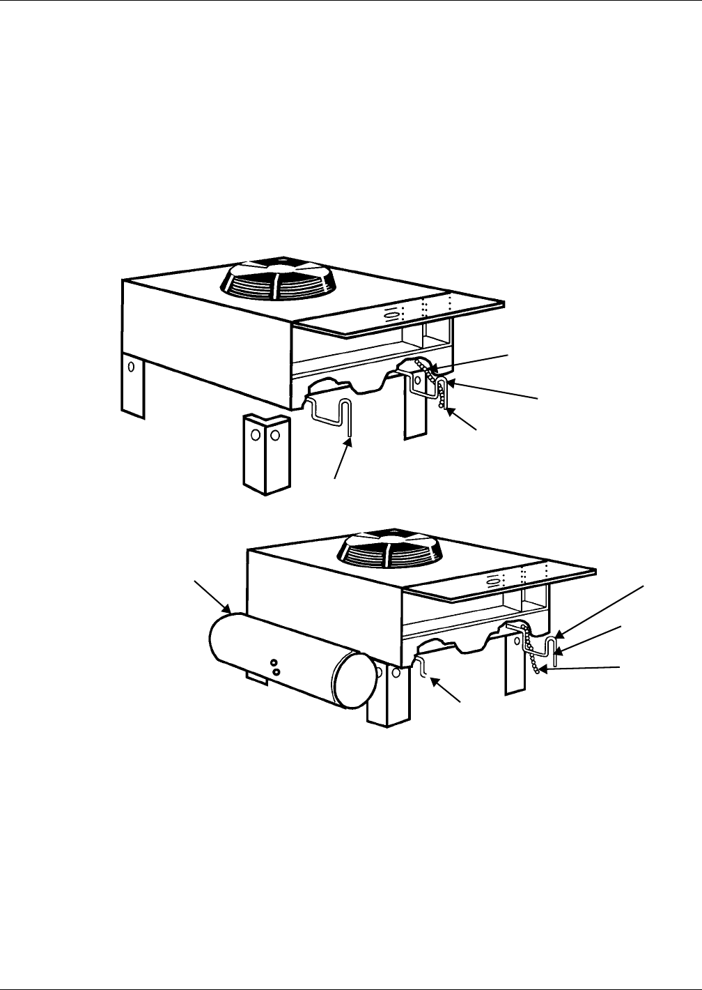
Figure 23 Outdoor fan/condenser configuration
7.4.7 Water/Glycol Cooled Condensers
Coaxial Condenser
Each water- or glycol-cooled module has a coaxial condenser that consists of a steel outside tube and a
copper inside tube.
Coaxial condensers do not normally require maintenance or replacement if the water supply is clean.
If your system operates at high head pressure with reduced capacity, and all other causes have been
eliminated, the coaxial condenser may be obstructed and needs to be replaced.
Secure each leg to condenser
frame at all points shown using
hardware provided.
Liquid line
* B
Hot gas line
Electric service
supplied by others
FAN SPEED CONDENSER
Lee-Temp heater pad
connection box
*B - Inverted traps are to be field-supplied and installed (typical). When installing traps, pro-
vide clearance for swing end of access door. Traps are to extend above base of coil by a
minimum of 7-1/2" (190 mm).
Liquid line
Electric
service
supplied by
others
Hot gas line
* B
LEE-TEMP CONDENSER