
User Manual


Table Of Contents
- Important Safety Instructions
- SAVE THESE INSTRUCTIONS
- 1.0 Introduction
- 2.0 Startup
- 3.0 Operation with iCOM Control
- 4.0 Liebert iCOM Display Components and Functions
- Figure 2 Liebert iCOM display components
- Table 1 Keyboard icons and functions
- Figure 3 Liebert iCOM default screen symbols
- 4.1 Navigating Through the Liebert iCOM Display
- 4.2 Changing Operational Settings
- 4.3 Changing Liebert iCOM’s Display Settings
- 4.4 Graphical Data Record
- 4.5 Liebert iCOM Service Menu Icons and Legend
- 4.6 Wiring for Unit-to-Unit Communications—U2U
- 4.7 Entering Network Setup Information
- 4.8 Viewing Multiple Units with a Networked Large Display
- 5.0 Operation
- 6.0 Alarm Descriptions
- 6.1 Standard Alarms
- 6.1.1 Change Filter
- 6.1.2 Compressor Overload
- 6.1.3 High Head Pressure
- 6.1.4 High Humidity
- 6.1.5 High Humidity and Low Humidity (Simultaneously)
- 6.1.6 High Temperature
- 6.1.7 High Temperature and Low Temperature (Simultaneously)
- 6.1.8 Humidifier Problem
- 6.1.9 Loss of Air Flow
- 6.1.10 Loss of Power
- 6.1.11 Low Humidity
- 6.1.12 Low Suction Pressure
- 6.1.13 Low Temperature
- 6.1.14 Main Fan Overload
- 6.1.15 Short Cycle
- 6.2 Optional Alarms
- 6.3 Set Alarms—User Menus
- 6.1 Standard Alarms
- 7.0 Component Operation and Maintenance
- 7.1 System Testing
- 7.2 Filters
- 7.3 Blower Package
- 7.4 Refrigeration System
- 7.4.1 Suction Pressure
- 7.4.2 Discharge Pressure
- 7.4.3 Superheat
- 7.4.4 Thermostatic Expansion Valve
- 7.4.5 Hot Gas Bypass Valve—Not Available on Digital Scroll Units
- 7.4.6 Air Cooled Condenser
- 7.4.7 Water/Glycol Cooled Condensers
- 7.4.8 Motorized Ball Valve—Digital Scroll Compressor
- 7.4.9 Regulating Valve—Scroll Compressor
- 7.4.10 Drycooler Settings
- 7.4.11 Compressor Oil
- 7.5 Compressor Replacement
- 7.6 Facility Fluid and Piping Maintenance for Water and Glycol Systems
- 7.7 Humidifier
- 8.0 Troubleshooting
- Table 12 Blower troubleshooting
- Table 13 Chilled water troubleshooting
- Table 14 Compressor and refrigeration system troubleshooting
- Table 15 Dehumidification troubleshooting
- Table 16 Glycol pump troubleshooting
- Table 17 Infrared humidifier troubleshooting
- Table 18 Steam generating humidifier troubleshooting
- Table 19 Reheat troubleshooting
- 9.0 Monthly Maintenance Inspection Checklist
- 10.0 Semiannual Maintenance Inspection Checklist
Component Operation and Maintenance
40
7.3.3 Air Distribution
All unit models are designed for constant volume air delivery. Therefore any unusual restrictions
within the air circuit must be avoided. For downflow models operating on a raised floor, refer to the
following table for recommended free area for proper air flow.
Grilles used in raised floors vary in size, the largest being 18" x 6" (46 cm x 15 cm). This type of grille
has approximately 56 in
2
(361 cm
2
) of free area. Perforated Panels are usually 2' x 2' (61 cm x 61 cm)
and have a nominal free area of approximately 108 to 144 in
2
(697 to 929 cm
2
).
NOTICE
Risk of airflow restriction. Can cause inefficient operation and equipment overheating.
In raised-floor use, all under-floor restrictions, such as clusters of cables or piping, must be
avoided because they may form barriers to airflow. Whenever possible, cables and pipes
should be run parallel to the airflow. Never stack cables or piping.
7.4 Refrigeration System
Each month, the components of the refrigeration system should be inspected for proper function and
signs of wear. Since, in most cases, evidence of malfunction is present prior to component failure, peri-
odic inspections can be a major factor in the prevention of most system failures.
Refrigerant lines must be properly supported and not allowed to vibrate against ceilings, floors or the
unit frame. Inspect all refrigerant lines every six months for signs of wear and proper support. Also
inspect capillary and equalizer lines from the expansion valve and support as necessary.
Each liquid line has a sight glass that indicates liquid refrigerant flow and the presence of moisture.
Bubbles in the sight glass indicate a shortage of refrigerant or a restriction in the liquid line. The
moisture indicator changes from green to yellow when moisture is present in the system.
7.4.1 Suction Pressure
Suction pressure will vary with load conditions. The low pressure switch will shut the compressor
down if suction pressure falls below the cut-out setting. High suction pressure reduces the ability of
the refrigerant to cool compressor components and can result in compressor damage. Minimum (pres-
sure switch cut-out setting) and maximum (design operating) suction pressures are in Table 6.
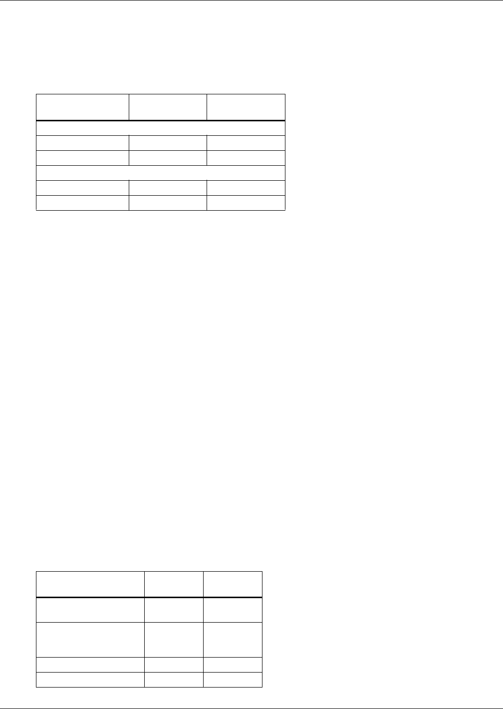
Table 5 Recommended free area ft
2
(m
2
) for grilles or perforated panels at output velocities of
550 and 600 fpm (2.8 and 3.1 m/s)
Model
550 FPM
(2.8 m/s)
600 FPM
(3.1 m/s)
60 Hz Units
3 Ton 3.3 (0.31) 3.0 (0.28)
5 Ton 5.1 (0.41) 4.7 (0.44)
50 Hz Units
3 Ton 3.3 (0.31) 3.0 (0.28)
5 Ton 4.7 (0.44) 4.3 (0.40)
Table 6 Suction pressures - R407c
System
Minimum
PSIG (kPa)
Maximum
PSIG (kPa)
Air w/FSC
(Fan Speed Control)
15 (103) 95 (654)
Air w/Lee-Temp Control
(Floodback head
pressure control)
20 (137) 95 (654)
Water Cooled 20 (137) 95 (654)
Glycol Cooled 20 (137) 95 (654)