
User Manual


Table Of Contents
- Important Safety Instructions
- SAVE THESE INSTRUCTIONS
- 1.0 Introduction
- 2.0 Startup
- 3.0 Operation with iCOM Control
- 4.0 Liebert iCOM Display Components and Functions
- Figure 2 Liebert iCOM display components
- Table 1 Keyboard icons and functions
- Figure 3 Liebert iCOM default screen symbols
- 4.1 Navigating Through the Liebert iCOM Display
- 4.2 Changing Operational Settings
- 4.3 Changing Liebert iCOM’s Display Settings
- 4.4 Graphical Data Record
- 4.5 Liebert iCOM Service Menu Icons and Legend
- 4.6 Wiring for Unit-to-Unit Communications—U2U
- 4.7 Entering Network Setup Information
- 4.8 Viewing Multiple Units with a Networked Large Display
- 5.0 Operation
- 6.0 Alarm Descriptions
- 6.1 Standard Alarms
- 6.1.1 Change Filter
- 6.1.2 Compressor Overload
- 6.1.3 High Head Pressure
- 6.1.4 High Humidity
- 6.1.5 High Humidity and Low Humidity (Simultaneously)
- 6.1.6 High Temperature
- 6.1.7 High Temperature and Low Temperature (Simultaneously)
- 6.1.8 Humidifier Problem
- 6.1.9 Loss of Air Flow
- 6.1.10 Loss of Power
- 6.1.11 Low Humidity
- 6.1.12 Low Suction Pressure
- 6.1.13 Low Temperature
- 6.1.14 Main Fan Overload
- 6.1.15 Short Cycle
- 6.2 Optional Alarms
- 6.3 Set Alarms—User Menus
- 6.1 Standard Alarms
- 7.0 Component Operation and Maintenance
- 7.1 System Testing
- 7.2 Filters
- 7.3 Blower Package
- 7.4 Refrigeration System
- 7.4.1 Suction Pressure
- 7.4.2 Discharge Pressure
- 7.4.3 Superheat
- 7.4.4 Thermostatic Expansion Valve
- 7.4.5 Hot Gas Bypass Valve—Not Available on Digital Scroll Units
- 7.4.6 Air Cooled Condenser
- 7.4.7 Water/Glycol Cooled Condensers
- 7.4.8 Motorized Ball Valve—Digital Scroll Compressor
- 7.4.9 Regulating Valve—Scroll Compressor
- 7.4.10 Drycooler Settings
- 7.4.11 Compressor Oil
- 7.5 Compressor Replacement
- 7.6 Facility Fluid and Piping Maintenance for Water and Glycol Systems
- 7.7 Humidifier
- 8.0 Troubleshooting
- Table 12 Blower troubleshooting
- Table 13 Chilled water troubleshooting
- Table 14 Compressor and refrigeration system troubleshooting
- Table 15 Dehumidification troubleshooting
- Table 16 Glycol pump troubleshooting
- Table 17 Infrared humidifier troubleshooting
- Table 18 Steam generating humidifier troubleshooting
- Table 19 Reheat troubleshooting
- 9.0 Monthly Maintenance Inspection Checklist
- 10.0 Semiannual Maintenance Inspection Checklist
Component Operation and Maintenance
38
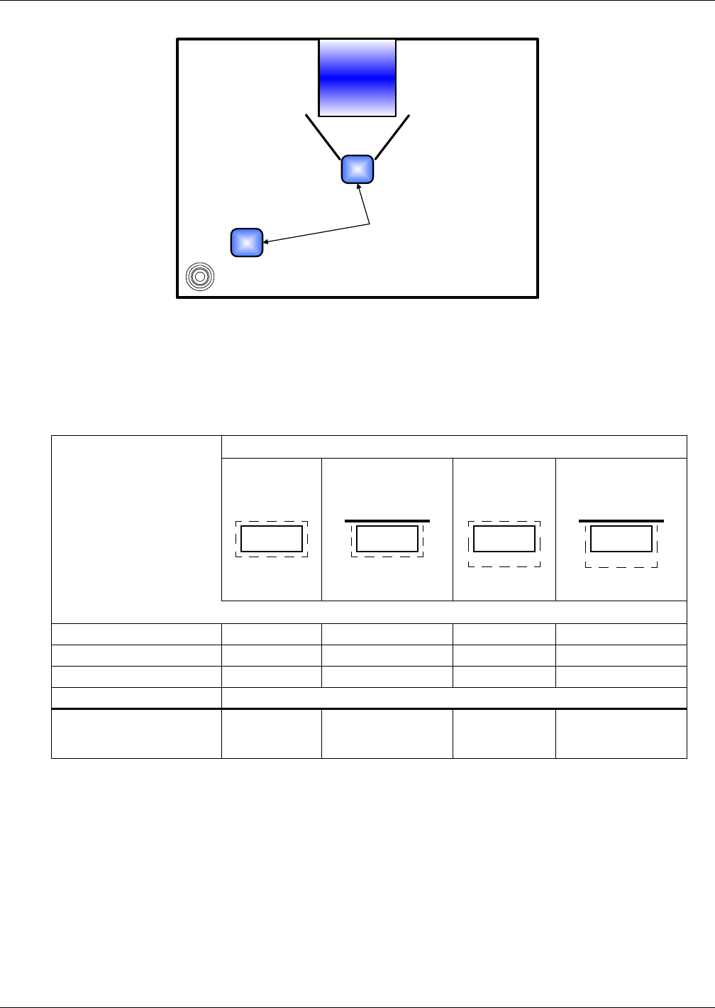
Figure 22 Recommended liquid sensor locations
The zone leak detection kit provides leak detection for a defined zone. This kit is ideal for perimeter
sensing or serpentine coverage of small areas. A simple, two-wire connection signals the alarms at a
Liebert environmental unit or at a monitoring panel. Run wires to the Liebert unit and connect them
to terminals 24 and 51, 55 or 56. The sensor utilizes Liebert's LT500Y leak detection cable. The kit is
offered with five different lengths of cable sized specifically for the type of Liebert Environmental unit
(see matrix below). Refer to matrix below for the recommended location of leak detection cable.
Remote Shutdown
A connection point is provided for customer supplied remote shutdown devices. This terminal strip is
located at the top of upflow units, and at the base of downflow units. Terminals 37 and 38 on the ter-
minal strip are jumpered when no remote shutdown device is installed.
Table 4 Zone leak detection kit installation scenarios
Scenarios
Upflow Unit
Detection
around
entire unit
Upflow Unit
Detection on sides
and
in front of unit
Downflow Unit
Detection
around
entire unit
Downflow Unit
Detection on sides
and
in front of unit
Distance From Unit, feet (m)
In back 2 (0.6) No cable behind 1 (0.3) No cable behind
On sides 2 (0.6) 2 (0.6) 1 (0.3) 1 (0.3)
In front 2 (0.6) 2 (0.6) 6 (1.8) 6 (1.8)
Unit (footprint-in.) Part Number
Liebert Challenger 3000
and Liebert Challenger ITR
(32.5 x 32.5)
LT460-Z30 LT460-Z20 LT460-Z30 LT460-Z25
Liebert Unit
Recommended Liebert
Liqui-tect location
Floor drain
2-ft clearance
in front
2-ft clearance
in front
6-ft clearance
in front
6-ft clearance
in front