
User Manual


Table Of Contents
- Important Safety Instructions
- SAVE THESE INSTRUCTIONS
- 1.0 Introduction
- 2.0 Startup
- 3.0 Operation with iCOM Control
- 4.0 Liebert iCOM Display Components and Functions
- Figure 2 Liebert iCOM display components
- Table 1 Keyboard icons and functions
- Figure 3 Liebert iCOM default screen symbols
- 4.1 Navigating Through the Liebert iCOM Display
- 4.2 Changing Operational Settings
- 4.3 Changing Liebert iCOM’s Display Settings
- 4.4 Graphical Data Record
- 4.5 Liebert iCOM Service Menu Icons and Legend
- 4.6 Wiring for Unit-to-Unit Communications—U2U
- 4.7 Entering Network Setup Information
- 4.8 Viewing Multiple Units with a Networked Large Display
- 5.0 Operation
- 6.0 Alarm Descriptions
- 6.1 Standard Alarms
- 6.1.1 Change Filter
- 6.1.2 Compressor Overload
- 6.1.3 High Head Pressure
- 6.1.4 High Humidity
- 6.1.5 High Humidity and Low Humidity (Simultaneously)
- 6.1.6 High Temperature
- 6.1.7 High Temperature and Low Temperature (Simultaneously)
- 6.1.8 Humidifier Problem
- 6.1.9 Loss of Air Flow
- 6.1.10 Loss of Power
- 6.1.11 Low Humidity
- 6.1.12 Low Suction Pressure
- 6.1.13 Low Temperature
- 6.1.14 Main Fan Overload
- 6.1.15 Short Cycle
- 6.2 Optional Alarms
- 6.3 Set Alarms—User Menus
- 6.1 Standard Alarms
- 7.0 Component Operation and Maintenance
- 7.1 System Testing
- 7.2 Filters
- 7.3 Blower Package
- 7.4 Refrigeration System
- 7.4.1 Suction Pressure
- 7.4.2 Discharge Pressure
- 7.4.3 Superheat
- 7.4.4 Thermostatic Expansion Valve
- 7.4.5 Hot Gas Bypass Valve—Not Available on Digital Scroll Units
- 7.4.6 Air Cooled Condenser
- 7.4.7 Water/Glycol Cooled Condensers
- 7.4.8 Motorized Ball Valve—Digital Scroll Compressor
- 7.4.9 Regulating Valve—Scroll Compressor
- 7.4.10 Drycooler Settings
- 7.4.11 Compressor Oil
- 7.5 Compressor Replacement
- 7.6 Facility Fluid and Piping Maintenance for Water and Glycol Systems
- 7.7 Humidifier
- 8.0 Troubleshooting
- Table 12 Blower troubleshooting
- Table 13 Chilled water troubleshooting
- Table 14 Compressor and refrigeration system troubleshooting
- Table 15 Dehumidification troubleshooting
- Table 16 Glycol pump troubleshooting
- Table 17 Infrared humidifier troubleshooting
- Table 18 Steam generating humidifier troubleshooting
- Table 19 Reheat troubleshooting
- 9.0 Monthly Maintenance Inspection Checklist
- 10.0 Semiannual Maintenance Inspection Checklist
Operation
27
5.0 OPERATION
The Liebert iCOM display for your Liebert cooling unit features an easy-to-use, menu-driven liquid
crystal display (LCD). All unit settings and parameters can be viewed and adjusted through three
menus: User, Service and Advanced. All active alarms are displayed on the LCD and annunciated.
The control is shipped from the factory with default selections for all necessary settings. Adjustments
can be made if the defaults do not meet your requirements.
References to menu items in this manual are followed by the main menu and the submenu where they
can be found.
For example:
• Temperature Setpoint (User Menu, Setpoints) - The Temperature Setpoint parameter is
located in the User menu under the Setpoints submenu.
• High Return Humidity (Service Menu, Set Alarms) - The High Return Humidity alarm is
located in the Service menu under the Set Alarms submenu.
5.1 Single Unit Functions
5.1.1 Unit/Fan Control
Start - Stop
Unit On means the fan output is activated. The unit can be switched On and Off from two inputs:
• Remote On/Off input
• Display button
Pressing the On/Off key on a small display will control only the cooling unit it is connected to regard-
less, of whether the cooling unit is a stand-alone unit or part of a network.
Pressing the On/Off key on a large display of a stand-alone cooling unit will control only that unit.
The effect of pressing the On/Off key on a large display connected to a network depends on the view:
System or Unit.
• In System view, pressing the On/Off key shows a warning asking for confirmation to shut down
the entire system.
• In Unit view, pressing the On/Off key affects only the unit being viewed, without a confirmation
request.
Each time a unit is powered On or Off, an event is added to the Event Log in the User menu.
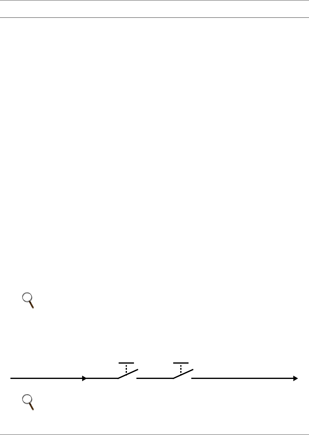
Figure 20 Start-stop priority switches
NOTE
Customer switches: remote On/Off (if used) and display On/Off switches are in series. A
cooling unit will start only if both switches are On; if one of these switches is Off, the unit will
stop. Safety devices within the unit are also in series and will shut the unit down if required.
NOTE
If Remote On/Off is not used, a jumper is inserted to bypass the switch.
Unit auto restart will begin once the control has booted.
Remote On / Off
Display On / Off