
User Manual


Table Of Contents
- Important Safety Instructions
- SAVE THESE INSTRUCTIONS
- 1.0 Introduction
- 2.0 Startup
- 3.0 Operation with iCOM Control
- 4.0 Liebert iCOM Display Components and Functions
- Figure 2 Liebert iCOM display components
- Table 1 Keyboard icons and functions
- Figure 3 Liebert iCOM default screen symbols
- 4.1 Navigating Through the Liebert iCOM Display
- 4.2 Changing Operational Settings
- 4.3 Changing Liebert iCOM’s Display Settings
- 4.4 Graphical Data Record
- 4.5 Liebert iCOM Service Menu Icons and Legend
- 4.6 Wiring for Unit-to-Unit Communications—U2U
- 4.7 Entering Network Setup Information
- 4.8 Viewing Multiple Units with a Networked Large Display
- 5.0 Operation
- 6.0 Alarm Descriptions
- 6.1 Standard Alarms
- 6.1.1 Change Filter
- 6.1.2 Compressor Overload
- 6.1.3 High Head Pressure
- 6.1.4 High Humidity
- 6.1.5 High Humidity and Low Humidity (Simultaneously)
- 6.1.6 High Temperature
- 6.1.7 High Temperature and Low Temperature (Simultaneously)
- 6.1.8 Humidifier Problem
- 6.1.9 Loss of Air Flow
- 6.1.10 Loss of Power
- 6.1.11 Low Humidity
- 6.1.12 Low Suction Pressure
- 6.1.13 Low Temperature
- 6.1.14 Main Fan Overload
- 6.1.15 Short Cycle
- 6.2 Optional Alarms
- 6.3 Set Alarms—User Menus
- 6.1 Standard Alarms
- 7.0 Component Operation and Maintenance
- 7.1 System Testing
- 7.2 Filters
- 7.3 Blower Package
- 7.4 Refrigeration System
- 7.4.1 Suction Pressure
- 7.4.2 Discharge Pressure
- 7.4.3 Superheat
- 7.4.4 Thermostatic Expansion Valve
- 7.4.5 Hot Gas Bypass Valve—Not Available on Digital Scroll Units
- 7.4.6 Air Cooled Condenser
- 7.4.7 Water/Glycol Cooled Condensers
- 7.4.8 Motorized Ball Valve—Digital Scroll Compressor
- 7.4.9 Regulating Valve—Scroll Compressor
- 7.4.10 Drycooler Settings
- 7.4.11 Compressor Oil
- 7.5 Compressor Replacement
- 7.6 Facility Fluid and Piping Maintenance for Water and Glycol Systems
- 7.7 Humidifier
- 8.0 Troubleshooting
- Table 12 Blower troubleshooting
- Table 13 Chilled water troubleshooting
- Table 14 Compressor and refrigeration system troubleshooting
- Table 15 Dehumidification troubleshooting
- Table 16 Glycol pump troubleshooting
- Table 17 Infrared humidifier troubleshooting
- Table 18 Steam generating humidifier troubleshooting
- Table 19 Reheat troubleshooting
- 9.0 Monthly Maintenance Inspection Checklist
- 10.0 Semiannual Maintenance Inspection Checklist
Liebert iCOM Display Components and Functions
17
4.6 Wiring for Unit-to-Unit Communications—U2U
The Liebert Challenger 3000/Liebert Challenger ITR with Liebert iCOM comes from the factory wired
for stand-alone operation. Multiple units can be set up in a network for efficiency, ease of operation
and easier control.
4.6.1 Liebert iCOM U2U Ethernet Network
The Liebert iCOM U2U network must be isolated from other network traffic. The network switch(es)
that connect Liebert iCOM controls need to be dedicated to supporting only Liebert iCOM communi-
cation. The U2U network cannot be connected to the building or IT network. If network communica-
tion is ever lost (failed network switch, etc.), all Liebert iCOM-controlled cooling units will continue to
operate as independent units.
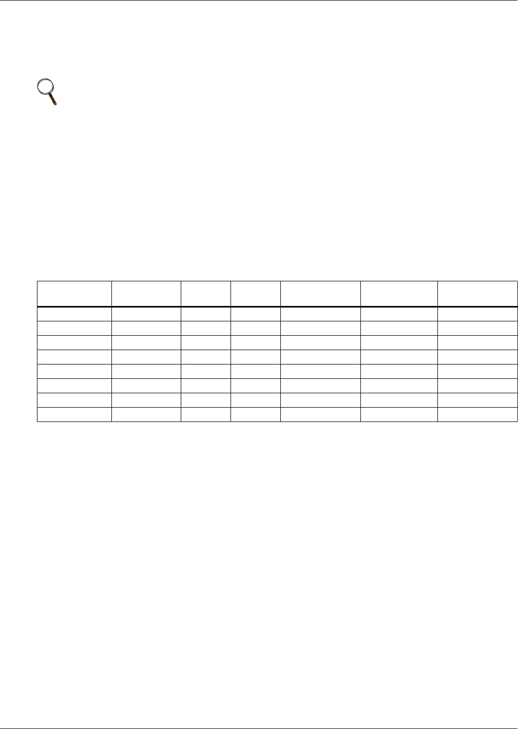
The Liebert iCOM control can support up to 64 nodes on one network. An input/output board, large
display and large wall-mount display are each considered one node. No more than 32 nodes may be
input/output boards (32 cooling units). A small display is not considered a node. Small displays con-
nect directly to input/output boards that do not have large displays attached to them. The following
table illustrates how a network can be configured.
Network communication can be configured during system startup by a Liebert-trained technician. For
technical issues contact:
Liebert Technical Service
1050 Dearborn Drive
Columbus, Ohio 43235
Telephone: 1-800-LIEBSRV (1-800-543-2778)
E-Mail: technicalservice@emersonnetworkpower.com
4.6.2 Wiring a Liebert iCOM U2U Network
Small Displays
Two cooling units, each with a small display: To network two cooling units, each with a small
display, connect a crossover CAT5 cable between the P64 connectors on each cooling unit’s Liebert
iCOM input/output board. A network switch is not needed, because the small display connects
directly to the Liebert iCOM.
Three or more units with small displays: To network three or more cooling units, each equipped
with a small display, connect a straight-through CAT5 Ethernet cable from the P64 connector on each
cooling unit’s Liebert iCOM input/output board to a common network switch (see Figure 13).
NOTE
U2U connections can be set up to link these units: Liebert Challenger 3000, Liebert Challenger
ITR, Liebert DS and Liebert CW. Each unit must be equipped with a Liebert iCOM.
Table 2 Sample Liebert iCOM network configurations
Sample
Configuration
Input/Output
Boards
Large
Displays
Small
Displays
Wall Mount
Large Displays
Private Switch
Required
Ports Required
on Switch
12020 NoNA
22021Yes 3
33030Yes 3
42110Yes 3
58441Yes13
6323200 Yes64
7322755 Yes64
8 32 0 32 32 Yes 64