
User Manual


Table Of Contents
- Important Safety Instructions
- SAVE THESE INSTRUCTIONS
- 1.0 Introduction
- 2.0 Startup
- 3.0 Operation with iCOM Control
- 4.0 Liebert iCOM Display Components and Functions
- Figure 2 Liebert iCOM display components
- Table 1 Keyboard icons and functions
- Figure 3 Liebert iCOM default screen symbols
- 4.1 Navigating Through the Liebert iCOM Display
- 4.2 Changing Operational Settings
- 4.3 Changing Liebert iCOM’s Display Settings
- 4.4 Graphical Data Record
- 4.5 Liebert iCOM Service Menu Icons and Legend
- 4.6 Wiring for Unit-to-Unit Communications—U2U
- 4.7 Entering Network Setup Information
- 4.8 Viewing Multiple Units with a Networked Large Display
- 5.0 Operation
- 6.0 Alarm Descriptions
- 6.1 Standard Alarms
- 6.1.1 Change Filter
- 6.1.2 Compressor Overload
- 6.1.3 High Head Pressure
- 6.1.4 High Humidity
- 6.1.5 High Humidity and Low Humidity (Simultaneously)
- 6.1.6 High Temperature
- 6.1.7 High Temperature and Low Temperature (Simultaneously)
- 6.1.8 Humidifier Problem
- 6.1.9 Loss of Air Flow
- 6.1.10 Loss of Power
- 6.1.11 Low Humidity
- 6.1.12 Low Suction Pressure
- 6.1.13 Low Temperature
- 6.1.14 Main Fan Overload
- 6.1.15 Short Cycle
- 6.2 Optional Alarms
- 6.3 Set Alarms—User Menus
- 6.1 Standard Alarms
- 7.0 Component Operation and Maintenance
- 7.1 System Testing
- 7.2 Filters
- 7.3 Blower Package
- 7.4 Refrigeration System
- 7.4.1 Suction Pressure
- 7.4.2 Discharge Pressure
- 7.4.3 Superheat
- 7.4.4 Thermostatic Expansion Valve
- 7.4.5 Hot Gas Bypass Valve—Not Available on Digital Scroll Units
- 7.4.6 Air Cooled Condenser
- 7.4.7 Water/Glycol Cooled Condensers
- 7.4.8 Motorized Ball Valve—Digital Scroll Compressor
- 7.4.9 Regulating Valve—Scroll Compressor
- 7.4.10 Drycooler Settings
- 7.4.11 Compressor Oil
- 7.5 Compressor Replacement
- 7.6 Facility Fluid and Piping Maintenance for Water and Glycol Systems
- 7.7 Humidifier
- 8.0 Troubleshooting
- Table 12 Blower troubleshooting
- Table 13 Chilled water troubleshooting
- Table 14 Compressor and refrigeration system troubleshooting
- Table 15 Dehumidification troubleshooting
- Table 16 Glycol pump troubleshooting
- Table 17 Infrared humidifier troubleshooting
- Table 18 Steam generating humidifier troubleshooting
- Table 19 Reheat troubleshooting
- 9.0 Monthly Maintenance Inspection Checklist
- 10.0 Semiannual Maintenance Inspection Checklist
Liebert iCOM Display Components and Functions
16
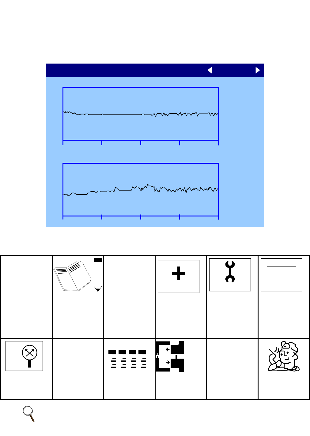
4.4 Graphical Data Record
The Graphical Data Record charts the average temperature from the return air temperature sensor
(see Figure 10). The temperature scales can be changed to expand or compress the data. The time
scale also can be altered to any of several selectable values. Changing the time scale eliminates all
previous graphical data and the unit will begin recording new data.
Figure 10 Temperature graph
4.5 Liebert iCOM Service Menu Icons and Legend
Figure 11 Liebert iCOM Service Menu icons
Setpoints
View and change
operational
setpoints
Unit Diary
Shows all program
changes and
maintenance
performed,
Maintenance/
Wellness
Settings
Shows all mainte-
nance records, cal-
culates next
maintenance date
Diagnostics/
Service Mode
Enter Diagnostics/
Service Mode for
troubleshooting
and repair; Large
Display Only
Set Alarms
Change settings for
alarms
Sensor
Calibration/Setup
Setup and calibrate
sensors for site
Network
Setup or alter
network setting.
Options Setup
Enter specific
settings for various
options
Service Contacts
Contains key
contact information
for service
NOTE
Menu shows icons only; text is explanatory and does not appear on the Liebert iCOM display.
UNIT 1
+11
RETURN AIR TEMPERATURE
73°F
-11
18ht:24h 12h 6h 09:21
+25
RETURN AIR HUMIDITY
50%
-25
18ht:24h 12h 6h 09:21
GRAPHS (system average )
°C / °F
% RH
SET
WELLNESS
SERVICE
SET
ALARMS
+ / -
NETWORK
SET
UP