
User Manual


Table Of Contents
- Important Safety Instructions
- SAVE THESE INSTRUCTIONS
- 1.0 Introduction
- 2.0 Startup
- 3.0 Operation with iCOM Control
- 4.0 Liebert iCOM Display Components and Functions
- Figure 2 Liebert iCOM display components
- Table 1 Keyboard icons and functions
- Figure 3 Liebert iCOM default screen symbols
- 4.1 Navigating Through the Liebert iCOM Display
- 4.2 Changing Operational Settings
- 4.3 Changing Liebert iCOM’s Display Settings
- 4.4 Graphical Data Record
- 4.5 Liebert iCOM Service Menu Icons and Legend
- 4.6 Wiring for Unit-to-Unit Communications—U2U
- 4.7 Entering Network Setup Information
- 4.8 Viewing Multiple Units with a Networked Large Display
- 5.0 Operation
- 6.0 Alarm Descriptions
- 6.1 Standard Alarms
- 6.1.1 Change Filter
- 6.1.2 Compressor Overload
- 6.1.3 High Head Pressure
- 6.1.4 High Humidity
- 6.1.5 High Humidity and Low Humidity (Simultaneously)
- 6.1.6 High Temperature
- 6.1.7 High Temperature and Low Temperature (Simultaneously)
- 6.1.8 Humidifier Problem
- 6.1.9 Loss of Air Flow
- 6.1.10 Loss of Power
- 6.1.11 Low Humidity
- 6.1.12 Low Suction Pressure
- 6.1.13 Low Temperature
- 6.1.14 Main Fan Overload
- 6.1.15 Short Cycle
- 6.2 Optional Alarms
- 6.3 Set Alarms—User Menus
- 6.1 Standard Alarms
- 7.0 Component Operation and Maintenance
- 7.1 System Testing
- 7.2 Filters
- 7.3 Blower Package
- 7.4 Refrigeration System
- 7.4.1 Suction Pressure
- 7.4.2 Discharge Pressure
- 7.4.3 Superheat
- 7.4.4 Thermostatic Expansion Valve
- 7.4.5 Hot Gas Bypass Valve—Not Available on Digital Scroll Units
- 7.4.6 Air Cooled Condenser
- 7.4.7 Water/Glycol Cooled Condensers
- 7.4.8 Motorized Ball Valve—Digital Scroll Compressor
- 7.4.9 Regulating Valve—Scroll Compressor
- 7.4.10 Drycooler Settings
- 7.4.11 Compressor Oil
- 7.5 Compressor Replacement
- 7.6 Facility Fluid and Piping Maintenance for Water and Glycol Systems
- 7.7 Humidifier
- 8.0 Troubleshooting
- Table 12 Blower troubleshooting
- Table 13 Chilled water troubleshooting
- Table 14 Compressor and refrigeration system troubleshooting
- Table 15 Dehumidification troubleshooting
- Table 16 Glycol pump troubleshooting
- Table 17 Infrared humidifier troubleshooting
- Table 18 Steam generating humidifier troubleshooting
- Table 19 Reheat troubleshooting
- 9.0 Monthly Maintenance Inspection Checklist
- 10.0 Semiannual Maintenance Inspection Checklist
Liebert iCOM Display Components and Functions
9
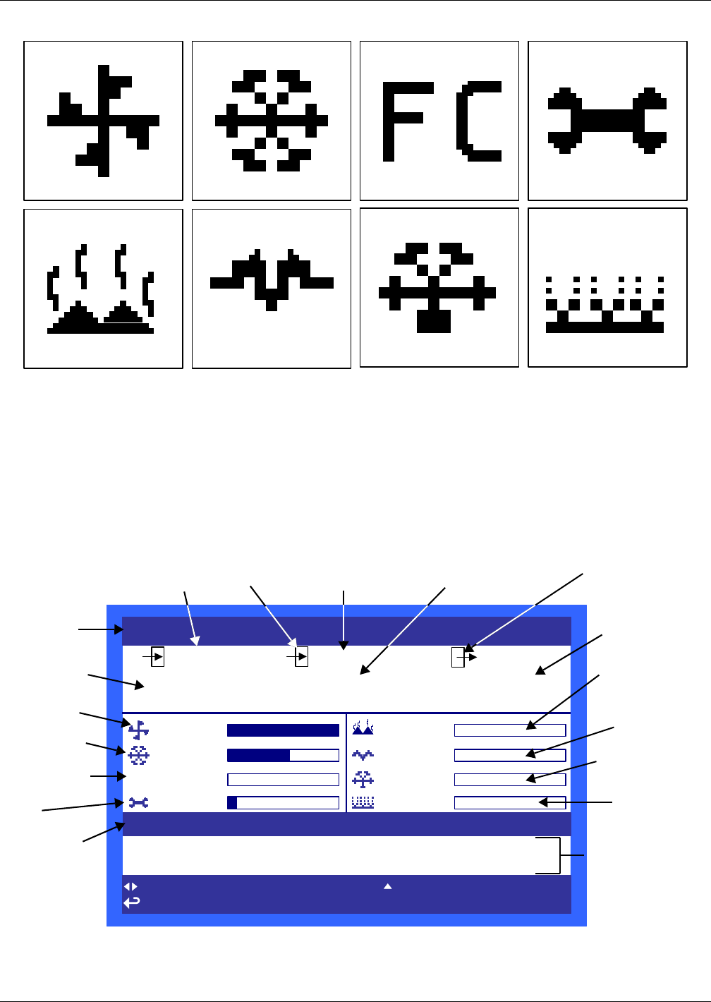
Figure 3 Liebert iCOM default screen symbols
4.1 Navigating Through the Liebert iCOM Display
Liebert iCOM displays icons and text for monitoring and controlling your Liebert cooling unit. The
number of icons and amount of text shown depends on the display size.
The Liebert iCOM offers two different types of views: graphical and simple. The graphical view is the
default; to set the simple view refer to 4.3 - Changing Liebert iCOM’s Display Settings. The Lie-
bert iCOM’s home screen is shown in Figure 4 (graphical view) and in Figure 5 (simple view).
Figure 4 Liebert iCOM default home screen—Graphical view
fan
cooling
maintenance
hot water
electric heat
dehumidification humidification
freecooling
7/29/2009 08 :28 (01) MSG UNIT ON
7/29/2009 08 :27 (01) MSG POWER ON
UNIT 1
7/29/2009 09 :18:07
50
72.0°F 50%
51.6
°F
%
SET
ACT
UNIT ON
for next /prev unit for system view
for menu for previous screen ? for help
ESC
73.6
°F
100%
60%
FC
0%
03/2010
0%
0%
0%
0%
System or
Unit # view
Temperature
Sensor Reading
Evaporator
Fan Speed
Percent
Cooling
Free-Cooling
Percentage
Next
Maintenance
Date and
Time
Temperature
Setpoint
Return Air
Humidity
Setpoint
Humidity Sensor
Reading
Supply Air (requires
optional supply air
sensor)
Supply
Air Temperature
Percent
Electric
Heating
Percent
Dehumidifying
System
(or Unit)
On/Off
Most recent Mes-
sage (MSG), Alarm
(ALM) or Warning
(WRN) with Date,
Time, Unit and
Description)
Percent
Hot Water
Heating