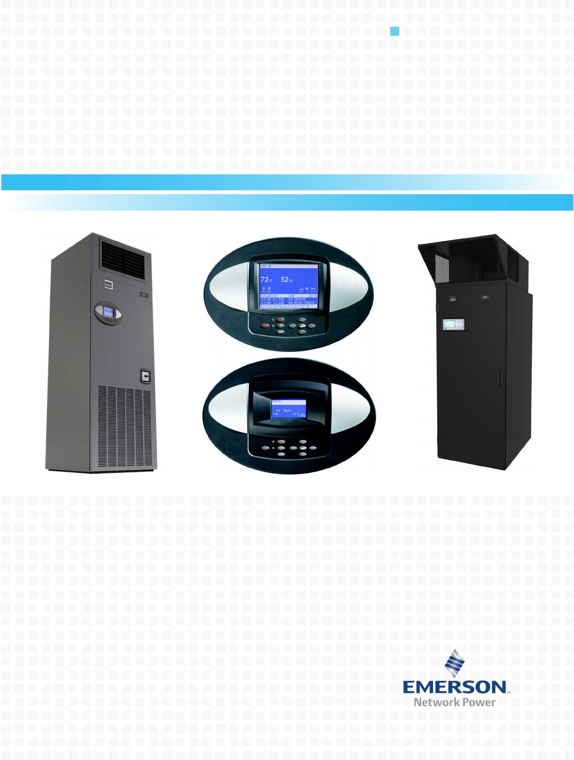
Precision Cooling For Business-Critical Continuity™ Liebert® Challenger™ 3000/Liebert Challenger ITR™ with Liebert iCOM® Control Operation & Maintenance Manual - 50 & 60Hz
TABLE OF CONTENTS IMPORTANT SAFETY INSTRUCTIONS . . . . . . . . . . . . . . . . . . . . . . . . . . . . . . . . . . . . . . . . . . . . . . . .1 SAVE THESE INSTRUCTIONS . . . . . . . . . . . . . . . . . . . . . . . . . . . . . . . . . . . . . . . . . . . . . . . . .1 1.0 INTRODUCTION . . . . . . . . . . . . . . . . . . . . . . . . . . . . . . . . . . . . . . . . . . . . . . . . . . . . . . . . . .3 1.1 System Descriptions . . . . . . . . . . . . . . . . . . . . . . . . . . . . . . . . . . . . . . . . . .
6.1 Standard Alarms . . . . . . . . . . . . . . . . . . . . . . . . . . . . . . . . . . . . . . . . . . . . . . . . . . . . . . . . . . . 32 6.1.1 6.1.2 6.1.3 6.1.4 6.1.5 6.1.6 6.1.7 6.1.8 6.1.9 6.1.10 6.1.11 6.1.12 6.1.13 6.1.14 6.1.15 6.2 Change Filter . . . . . . . . . . . . . . . . . . . . . . . . . . . . . . . . . . . . . . . . . . . . . . . . . . . . . . . . . . . . . . . Compressor Overload . . . . . . . . . . . . . . . . . . . . . . . . . . . . . . . . . . . . . . . . . . . . . . . . . . . . . .
7.6 Facility Fluid and Piping Maintenance for Water and Glycol Systems . . . . . . . . . . . . . . . . 49 7.7 Humidifier. . . . . . . . . . . . . . . . . . . . . . . . . . . . . . . . . . . . . . . . . . . . . . . . . . . . . . . . . . . . . . . . . 50 7.7.1 7.7.2 Infrared Humidifier . . . . . . . . . . . . . . . . . . . . . . . . . . . . . . . . . . . . . . . . . . . . . . . . . . . . . . . . . . 50 Steam Generating Humidifier . . . . . . . . . . . . . . . . . . . . . . . . . . . . . . . . . . . . . .
TABLES Table 1 Table 2 Table 3 Table 4 Table 5 Table 6 Table 7 Table 8 Table 9 Table 10 Table 11 Table 12 Table 13 Table 14 Table 15 Table 16 Table 17 Table 18 Table 19 Keyboard icons and functions. . . . . . . . . . . . . . . . . . . . . . . . . . . . . . . . . . . . . . . . . . . . . . . . . . . . . . . 8 Sample Liebert iCOM network configurations . . . . . . . . . . . . . . . . . . . . . . . . . . . . . . . . . . . . . . . . 17 Set alarms—User Menus . . . . . . . . . . . . . . . . . . . . . . . . . . .
IMPORTANT SAFETY INSTRUCTIONS SAVE THESE INSTRUCTIONS This manual contains important safety instructions that should be followed during the installation and maintenance of the Liebert Challenger 3000/Liebert Challenger ITR with Liebert iCOM. Read this manual thoroughly before attempting to install or operate this unit. Only qualified personnel should move, install or service this equipment. Adhere to all warnings, cautions and installation, operating and safety instructions on the unit and in this manual.
! WARNING Risk of high-speed moving parts. Can cause injury or death. Disconnect all local and remote electric power supplies before working in the unit. Do not operate upflow units without installing a plenum, ductwork or guard over the blower opening(s) on the top of the unit cabinet. Ductwork must be connected to the blower(s), or a plenum must be installed on the blower deck for protection from rotating blower wheel(s) on upflow units. ! CAUTION Risk of contact with hot surfaces. Can cause injury.
Introduction 1.0 INTRODUCTION 1.1 System Descriptions The Liebert Challenger 3000™ and Liebert Challenger ITR™ Precision Cooling systems are available in several configurations. 1.1.1 Compressorized Systems NOTE Compressorized systems may be a self-contained system, with the compressor in the Liebert Challenger 3000/Liebert Challenger ITR unit, or a split system, with the compressor in a separate condensing unit.
Startup 2.0 STARTUP Before beginning startup, make certain that unit was installed according to the instructions in the installation manual, SL-11962. Verify that the fan shipping bolt has been removed, the check valve has been installed (on air cooled units), and that the scroll compressor is rotating in the proper direction. All exterior panels must be in place with the front panel open. Locate the startup form supplied with your unit documents.
Startup 14. 15. 16. 17. 18. Check for unusual noises and vibration. Check all refrigerant and fluid lines for leaks. Test all functions of your unit for proper operation. Close high voltage dead front cover and latch. Close front accent panel and latch. Return completed startup form to: Liebert Corporation Warranty Registration 1050 Dearborn Drive P.O.
Operation with iCOM Control 3.0 OPERATION WITH ICOM CONTROL The Liebert iCOM™ control offers the highest capabilities in unit control, communication and monitoring of Liebert mission-critical cooling units. Liebert iCOM may be used to combine multiple cooling units into a team that operates as a single entity, enhancing the already-high performance and efficiency of Liebert’s units. 3.
Liebert iCOM Display Components and Functions 4.0 LIEBERT ICOM DISPLAY COMPONENTS AND FUNCTIONS The small and the large display have a common key layout, as shown in Figure 2. Figure 2 Liebert iCOM display components Liquid Crystal Display LED Status Indicators (top LED is red or flashing red; bottom LED is green or amber) ? ESC Large Liebert iCOM Display shown - Keypad and LEDs are identical on all displays.
Liebert iCOM Display Components and Functions Table 1 Icon ? ESC Keyboard icons and functions Key Name Function On/Off Key Controls the operational state of the cooling unit. Alarm Key Silences an alarm. Help Key Accesses integrated help menus. ESCape Key Returns to the previous display view. Enter Key Confirms all selections and selects icons or text. Increase Key (Up Arrow) Moves upward in a menu or increases the value of a selected parameter.
Liebert iCOM Display Components and Functions Figure 3 4.1 Liebert iCOM default screen symbols fan cooling hot water electric heat freecooling maintenance dehumidification humidification Navigating Through the Liebert iCOM Display Liebert iCOM displays icons and text for monitoring and controlling your Liebert cooling unit. The number of icons and amount of text shown depends on the display size. The Liebert iCOM offers two different types of views: graphical and simple.
Liebert iCOM Display Components and Functions Figure 5 Liebert iCOM default home screen—Simple view Return Air Temperature Setpoint System or Unit # view Temperature Sensor Reading Evaporator Fan Speed Percent Cooling Date and Time Return Air Humidity Setpoint 72.0°F 50% 74.1 °F 50 Supply Air Setpoint Supply Air Temperature UNIT 1 52.0°F SET 51.
Liebert iCOM Display Components and Functions 4.1.2 Accessing Menus and Settings Viewing Data No password is required to view data or settings. To view data: 1. 2. 3. 4. From the home screen, press the Enter key to view the User Menu (see Figure 8). Press Enter again to highlight the first icon. Use the keyboard’s arrow keys to move to the icon for the data you wish to view. Once that icon is highlighted, press Enter again to open that menu. • If a password is required, see 4.1.3 - Entering the Password.
Liebert iCOM Display Components and Functions 4.1.4 Accessing Submenus To access the User, Service or Advanced menu, press the Enter or down arrow key while viewing the Status menu of the unit you wish to access. The User menu will be displayed first. To view the Service or Advanced menus, press the right arrow key. Accessing Submenus on Small Displays While viewing the menu you wish to access (User, Service or Advanced), use the up and down arrow keys to scroll through the icons page-by-page.
Liebert iCOM Display Components and Functions Figure 7 Menu tree—Large and small displays, stand-alone or networked Status Menu – System View (Large Display Only) Unit 1 will be displayed in the top left corner of the screen on the large display only.
Liebert iCOM Display Components and Functions 4.2 Changing Operational Settings Changes to the Liebert Challenger 3000/Liebert Challenger ITR’s operation settings in the Set Alarms and Setpoints menus require a password. 1. 2. 3. 4. 5. 6. 7. 8. 9. 10. Figure 8 From the home screen, press the Enter key to view the User Menu (see Figure 8). Press Enter again to highlight the first icon. Use the keyboard’s arrow keys to move to the icon for the data you wish to change.
Liebert iCOM Display Components and Functions 4.3 Changing Liebert iCOM’s Display Settings No password is required to change the way Liebert iCOM displays data. The Display Setup controls how the unit shows data, such as temperature, date and time. To change the display settings: 1. 2. 3. 4. 5. 6. 7. 8. 9. Figure 9 From the home screen, press the Enter key to view the User Menu (see Figure 8). Press Enter again to highlight the first icon. Use the keyboard’s arrow keys to move to the Display Setup icon.
Liebert iCOM Display Components and Functions 4.4 Graphical Data Record The Graphical Data Record charts the average temperature from the return air temperature sensor (see Figure 10). The temperature scales can be changed to expand or compress the data. The time scale also can be altered to any of several selectable values. Changing the time scale eliminates all previous graphical data and the unit will begin recording new data.
Liebert iCOM Display Components and Functions 4.6 Wiring for Unit-to-Unit Communications—U2U The Liebert Challenger 3000/Liebert Challenger ITR with Liebert iCOM comes from the factory wired for stand-alone operation. Multiple units can be set up in a network for efficiency, ease of operation and easier control. NOTE U2U connections can be set up to link these units: Liebert Challenger 3000, Liebert Challenger ITR, Liebert DS and Liebert CW. Each unit must be equipped with a Liebert iCOM. 4.6.
Liebert iCOM Display Components and Functions Large Displays A network switch is required to enable Ethernet communication on one or more cooling units with large displays. Each cooling unit with a large display requires two straight-through Ethernet cables from a network switch. One cable connects to port P64 on the Liebert iCOM input/output board and the other straight-through cable connects to the female-female coupler provided with the unit.
Liebert iCOM Display Components and Functions Figure 12 U2U network setup diagram Display Service /Network Liebert iCom Display Menu IP Address: 192.168.001.001 U2U Address:1 Group #: 1 --------------------------------------- Display Service /Network Liebert Challenger Control Board Menu Display Service /Network Liebert Challenger Control Board Menu IP Address: 192.168.001.002 U2U Address: 2 Group #: 1 IP Address: 192.168.001.
Liebert iCOM Display Components and Functions Notes on Wiring for a U2U Network—Refer to Figures 13 and 15 1. See unit electrical schematic. 2. Cable ‘A’ and ‘B’ are provided with each unit.
Liebert iCOM Display Components and Functions Figure 13 Liebert iCOM wiring—Unit as shipped CAN Cable Liebert IntelliSlot Power Supply Ribbon Cables Liebert IntelliSlot 1 Liebert IntelliSlot 2 See Note 3 P64A Connection Located Near I/O Board Standard Small Graphics Display (Rear View) Cable 'A' Red Crossover Ethernet Cable Not Used Cable 'B' CAN Cable See Note 2 Cable 'C' Liebert iCOM Microprocessor and I/O Board See table for plug assignments T1 Unit Control Transformer Cable†‘D’ See No
Liebert iCOM Display Components and Functions Figure 14 Wiring a small display for U2U network operation CAN Cable Cable 'C' P64A Connection Located Near I/O Board Not Used Standard Small Graphics Display (Rear View) U2U Networking Switch (Field-Supplied) Liebert iCOM I/O Board Straight-Through Ethernet Cable 194273 22 To / From Other Networked Units
Liebert iCOM Display Components and Functions Figure 15 Wiring a large display for U2U network operation CAN Cable Red Crossover Ethernet Cable Crossover Coupler (See Note 6) Cable 'C' See Note 4 Not Used Cable 'D' P64A Connection Located Near I/O Board Optional Large Graphics Display (Rear View) Customer Connection Point See Note 6 U2U Networking Switch (Field-Supplied) Liebert iCOM I/O Board Straight-Through Ethernet Cables 23 To / From Other Networked Units 194273
Liebert iCOM Display Components and Functions Figure 16 Liebert iCOM input-output control board P65 P61 P63 P64 (RJ-45 Jack) P67 P66 24
Liebert iCOM Display Components and Functions 4.7 Entering Network Setup Information Setting up a U2U network requires setting a unique IP addresses for each unit, choosing a U2U address and designating the U2U group. Refer to Figure 17 for the setup screen for the control board (installed inside the Liebert Challenger 3000/Liebert Challenger ITR) and Figure 18 for the setup screen for the Liebert iCOM on the front of the Liebert Challenger 3000/Liebert Challenger ITR.
Liebert iCOM Display Components and Functions 4.8 Viewing Multiple Units with a Networked Large Display When you first wake up the control, press the ESC key to return to the System view Status menu. This view shows an average of all the units on the network and any alarms present. To view a specific unit on the network, press either the enter key or down arrow key. When you do this, you will see the word System in the top left of the screen change to a unit number.
Operation 5.0 OPERATION The Liebert iCOM display for your Liebert cooling unit features an easy-to-use, menu-driven liquid crystal display (LCD). All unit settings and parameters can be viewed and adjusted through three menus: User, Service and Advanced. All active alarms are displayed on the LCD and annunciated. The control is shipped from the factory with default selections for all necessary settings. Adjustments can be made if the defaults do not meet your requirements.
Operation ! WARNING Risk of electric shock. Can cause injury or death. The Liebert iCOM microprocessor does not isolate power from the unit, even in the “Unit Off” mode. Some internal components require and receive power even during the “Unit Off” mode of Liebert iCOM control. The only way to ensure that there is NO voltage inside the unit is to install and open a remote disconnect switch. Refer to unit electrical schematic.
Operation Pump Down—Air Cooled with Condenser Only Units NOTE Pump down activation is determined by the type of unit; these units do not have a pump-down function: Glycol, GLYCOOL and remote condensing units. The Pump Down operation is performed to protect the compressor oil from being diluted with liquid refrigerant, which helps ensure that the compressor is properly lubricated for the next startup.
Operation Evaluate the start operation of the unit (with pump down). 1. Close LLSV 2. Wait for LPS to make or ignore for WSK time If LPS is made before WSK has expired, allow the compressor to continue running, if not then stop compressor and alarm low pressure alarm. 3. Once LPS makes start compressor. 4. Verify the alarm phrase for the WSK and the low pressure switch. 5.2 Control Types 5.2.
Operation 5.2.3 Intelligent Control (Chilled Water Only) The intelligent control operates from a set of general rules that define how the control output should be adjusted for different system conditions. The rules are designed to duplicate the actions that an experienced human operator would take if manually controlling the system. Just as an operator might take several things into consideration before making a temperature control decision, the intelligent control can be programmed to do likewise.
Alarm Descriptions 6.0 ALARM DESCRIPTIONS The Liebert iCOM will audibly and visually annunciate all enabled alarms. Alarms are wired from Terminal 24 through a normally open contact to locations 50, 51, 55 and 56, respectively, for alarms 1 through 4. The alarms can be delayed from 0 to 255 seconds. The alarms can be designated as WARNING, URGENT, or DISABLED. Alarms designated as WARNINGS are annunciated after the Time Delay, but do not energize the Common Alarm Relay.
Alarm Descriptions 6.1.3 High Head Pressure Compressor high head is monitored with a pressure switch. One SPDT pressure switch is used for the compressor in the unit. If head pressure exceeds 360 PSIG, the switch opens the compressor contactor and sends an input signal to the control. On a self-contained system, the head pressure switch located at the compressor requires a manual reset and the alarm condition to be acknowledged on the front display panel.
Alarm Descriptions 6.1.9 Loss of Air Flow A differential air pressure switch is used to indicate loss of air flow in Liebert Challenger 3000/Liebert Challenger ITR units. Check for blockage of unit air outlet or inlet. Check blower motor fuses and overload reset. Check for broken belts. Make sure blower wheels are tight to shaft. Run diagnostics to see if the fan contactor is working properly. 6.1.
Alarm Descriptions 6.2 Optional Alarms 6.2.1 Loss of Water Flow Available only with 3-way valves and occurs when no water flow is detected in the chilled water or condenser water supply line. An optional flow switch is required for this alarm. Check for service valves closed, pumps not working, etc. 6.2.2 Smoke Detected Smoke is detected in the return air by an optional Liebert Smoke Detector. Check for source of smoke or fire, and follow appropriate emergency procedures. 6.2.
Component Operation and Maintenance 7.0 COMPONENT OPERATION AND MAINTENANCE 7.1 System Testing 7.1.1 Environmental Control Functions The performance of all control circuits can be tested by actuating each of the main functions. This is done by temporarily changing the setpoints. Cooling To test the cooling function, set the setpoint for a temperature of 10°F (5°C) below room temperature. A call for cooling should be seen and the equipment should begin to cool. A high temperature alarm may come On.
Component Operation and Maintenance Control Transformer and Fuses The control system is divided into four separate circuits. The control voltage circuits are individually protected by fuses located on the transformer/fuse board. If any of the fuses are blown, first eliminate shorts, then use spare fuses supplied with unit. Use only type and size of fuse specified for your unit. The small isolation transformer on the board supplies 24 volts to the main control board. The transformer is internally protected.
Component Operation and Maintenance Figure 22 Recommended liquid sensor locations Liebert Unit Recommended Liebert Liqui-tect location Floor drain The zone leak detection kit provides leak detection for a defined zone. This kit is ideal for perimeter sensing or serpentine coverage of small areas. A simple, two-wire connection signals the alarms at a Liebert environmental unit or at a monitoring panel. Run wires to the Liebert unit and connect them to terminals 24 and 51, 55 or 56.
Component Operation and Maintenance 7.2 Filters Filters are usually the most neglected item in an environmental control system. To maintain efficient operation, they should be checked monthly and changed as required. Because replacement intervals vary with environmental condition and filter type, each unit is equipped with a filter clog switch. This warns of restricted airflow through the filter compartment by activating the Change Filter alarm. Turn power Off before replacing filters.
Component Operation and Maintenance 7.3.3 Air Distribution All unit models are designed for constant volume air delivery. Therefore any unusual restrictions within the air circuit must be avoided. For downflow models operating on a raised floor, refer to the following table for recommended free area for proper air flow. Recommended free area ft2 (m2) for grilles or perforated panels at output velocities of 550 and 600 fpm (2.8 and 3.1 m/s) Table 5 550 FPM (2.8 m/s) 600 FPM (3.1 m/s) 3 Ton 3.3 (0.
Component Operation and Maintenance 7.4.2 Discharge Pressure Discharge Pressure can be increased or decreased by load conditions or condenser efficiency. The high pressure switch will shut the compressor down at its cut-out setting. Refer to Table 7, below. Table 7 Discharge pressures System Design Discharge Pressure PSIG (kPa) Air Cooled Water/Glycol Cooled 7.4.
Component Operation and Maintenance 7.4.5 Hot Gas Bypass Valve—Not Available on Digital Scroll Units Operation—Self-Contained Units The hot gas bypass is inserted between the compressor discharge line and the leaving side of the expansion valve through the side outlet distributor. The system, with normal operation when the evaporator is under full load, will maintain enough pressure on the leaving side of the hot gas valve to keep the valve port closed.
Component Operation and Maintenance Checking Refrigerant Charge (Lee–Temp/Flood Back Head Pressure Control) The system refrigerant level must be checked periodically. To do so: 1. Adjust temperature setpoint in the unit so that the compressor will run continuously. 2. The refrigerant level is visible through two sight glasses on the receiver and will vary with ambient temperature. a. 40°F (4.4°C) and lower — Midway on the bottom sight glass. b. 40 to 60°F (4.4 to 15.
Component Operation and Maintenance 7.4.8 Motorized Ball Valve—Digital Scroll Compressor On water-cooled and glycol-cooled digital scroll units, the discharge pressure is controlled by a motorized ball valve. During unloaded operation, the pressure changes during each digital cycle could result in excessive repositions with a pressure operated water regulating valve.
Component Operation and Maintenance To raise the head pressure setting, turn the adjusting screw counterclockwise until the desired setting is obtained. Figure 24 Johnson Controls valve adjustment Range Spring Valve Spring Guide Range Adjustment Screw Top Retainer Insert screwdrivers under the valve spring guide. Manual Flushing—The valve may be flushed by inserting a screwdriver or similar tool under the two sides of the main spring and lifting.
Component Operation and Maintenance Manual Flushing—The valve may be flushed by rotating the socket head screw clockwise. This screw must be in the OUT position (counterclockwise) for normal valve operation. Valve Disassembly 1. Shut off the water supply by using isolating valves. 2. Relieve the tension on the main spring by turning the adjusting screw (or collar) as far as it will go (provide a container to catch water below the valve). 3. Remove four screws extending through the main spring housing. 4.
Component Operation and Maintenance 7.4.11 Compressor Oil NOTICE Risk of improper compressor lubrication. Can cause compressor and refrigerant system damage. Failure to use oil types, viscosities and quantities recommended by the compressor manufacturer may reduce compressor life and void the compressor warranty. See oil types specified in Table 10. • Do NOT mix polyol ester (POE) and mineral-based oils. • Do NOT mix oils of different viscosities.
Component Operation and Maintenance 7.5.2 Standard Scroll Compressor Replacement Infrequently a fault in the motor insulation may result in a motor burn, but burnouts rarely occur in a properly installed system. Of those that do, most are the effects of mechanical or lubrication failures, resulting in the burnout as a secondary consequence. If problems that can cause compressor failures are detected and corrected early, a large percentage can be prevented.
Component Operation and Maintenance Three-phase power must be connected to the unit line voltage terminals in the proper sequence so that the scroll compressor rotates in the proper direction. Rotation in the wrong direction will result in poor performance and compressor damage. Record compressor motor connections when removing a failed compressor. Wire the replacement compressor motor the same way to maintain proper rotation direction. 7.5.3 Digital Scroll Compressor Replacement Procedure 1. 2. 3. 4. 5.
Component Operation and Maintenance 7.7 Humidifier 7.7.1 Infrared Humidifier During normal humidifier operation, deposits of mineral solids will collect in the humidifier pan. This should be cleaned out periodically to ensure efficient operation. Each water supply has different characteristics, so the time interval between cleanings must be determined locally. A monthly check (and cleaning if necessary) is recommended.
Component Operation and Maintenance Changing Humidifier Lamps 1. 2. 3. 4. Open disconnect switch. Open front panel. Remove screws securing line voltage compartment cover, then remove the cover. In line voltage compartment, disconnect one end of the purple jumpers, then locate the burned out bulb with a continuity meter. 5. Remove humidifier pan. Refer to Removing the Pan on page 50. 6. Remove lamp brackets (2) under lamps. Figure 26 Infrared humidifier lamps Humidifier Lamps 7.
Component Operation and Maintenance Autoflush Controls Use the LCD display, menu, and keys on the front control panel to program the autoflush controls. 7.7.2 Steam Generating Humidifier Steam generating humidifiers are designed to operate in voltage ranges from 200 to 575 volts and generate 11 pounds (5 kg) of steam per hour. These humidifiers operate efficiently over a wide range of water quality conditions and automatically adjust to changes in the conductivity of water.
Component Operation and Maintenance Operation 1. During startup, when the humidity control calls for humidification, the fill valve opens and allows water to enter the canister. When the water level reaches the electrodes, current flows and the water begins to warm. The canister fills until the amperage reaches the setpoint and the fill valve closes. As the water warms, its conductivity increases and the current flow, in turn, rises.
Component Operation and Maintenance Replacing the Canister Over a period of operation, the humidifier electrodes become coated with mineral solids. This coating insulates the electrodes and decreases the current flow. To maintain humidifier capacity, the water level slowly rises to expose fresh electrode. Eventually, the entire electrode becomes coated and the water level reaches the top. At this point, the canister full alarm is activated and the output begins to fall.
Component Operation and Maintenance Circuit Board Adjustments ! WARNING Risk of electric shock. Can cause injury or death. The Liebert iCOM microprocessor does not isolate power from the unit, even in the “Unit Off” mode. The only way to ensure that there is NO voltage inside the unit is to install and open a remote disconnect switch. Refer to unit electrical schematic. Only properly trained and qualified personnel should perform adjustment of the circuit board.
Troubleshooting 8.0 TROUBLESHOOTING Use this section to assist in troubleshooting your unit. Also refer to 6.0 - Alarm Descriptions. Suggestions are grouped by product function for convenience. ! WARNING Risk of electric shock. Can cause injury or death. The Liebert iCOM microprocessor does not isolate power from the unit, even in the “Unit Off” mode. Some internal components require and receive power even during the “Unit Off” mode of Liebert iCOM control.
Troubleshooting Table 14 Compressor and refrigeration system troubleshooting Symptom Possible Cause Check or Remedy Power Off Check main switch, fuses or CBs and wiring Current overload open Re-set units with overload option manually. Allow compressor to cool for internal overloads to reset. Loose electrical connections Tighten connections Compressor motor burned out Check and replace compressor if defective. No call for cooling Check monitor status.
Troubleshooting Table 14 Compressor and refrigeration system troubleshooting (continued) Symptom Possible Cause Check or Remedy Defective or improperly set expansion valve Increase superheat or replace valve Evaporator fan motor or belt Correct problem or replace fan motor and/ or belts. Low condensing pressure Check head pressure control device Slipping belts Inspect and adjust Compressor rotation in reverse direction. Check for proper power phase wiring to unit and to compressor motor.
Troubleshooting Table 15 Dehumidification troubleshooting Symptom No dehumidification Table 16 Possible Cause Check or Remedy Control not calling for dehumidification Check monitor status. Compressor contactor not pulling in See 7.5.1 - Compressor Functional Check and Table 14. Compressor won't run; fuse blown or CB tripped See 7.5.1 - Compressor Functional Check and Table 14. Check fuses or CBs and contacts.
Troubleshooting Table 18 Steam generating humidifier troubleshooting Symptom Possible Cause Check or Remedy Check drain valve to ensure that it drains freely. Check and replace if defective. False canister full indication Foaming Check water supply. If commercially softened, reconnect to raw water supply. If connected to hot water reconnect to cold water. Main 24 VAC fuse or circuit breaker trips Shorts or loose connections Check the wiring connections of the 24 VAC circuit.
Troubleshooting Table 18 Steam generating humidifier troubleshooting (continued) Symptom Possible Cause Check or Remedy Drain valve clogged or defective Verify that drain valve operates freely when activated. Clean valve and replace coil or valve if defective. Flush canister several times and replace if arcing persists. Improper water supply If water is commercially softened, reconnect humidifier to raw water supply, drain canister, and restart If connected to hot supply, reconnect to cold water.
Monthly Maintenance Inspection Checklist 9.0 MONTHLY MAINTENANCE INSPECTION CHECKLIST Date:_______________________________________ Prepared by:_________________________________ Model #:_____________________________________ Serial #:____________________________________ Filters ___ 1. Restricted air flow ___ 2. Check filter switch ___ 3. Wipe section clean Steam Generating Humidifier ___ 1. Check canister for deposits ___ 2. Check condition of steam hoses ___ 3.
Semiannual Maintenance Inspection Checklist 10.0 SEMIANNUAL MAINTENANCE INSPECTION CHECKLIST Date:________________________________________ Prepared by:_________________________________ Model #:_____________________________________ Serial #:_____________________________________ Filters Steam Generating Humidifier ___ 1. Restricted air flow ___ 2. Check filter switch ___ 3. Wipe section clean ___ 1. ___ 2. ___ 3. ___ 4. Blower Section ___ 1. ___ 2. ___ 3. ___ 4.
Semiannual Maintenance Inspection Checklist 64
Ensuring The High Availability Of Mission-Critical Data And Applications. Emerson Network Power, the global leader in enabling business-critical continuity, ensures network resiliency and adaptability through a family of technologies—including Liebert power and cooling technologies—that protect and support business-critical systems. Liebert solutions employ an adaptive architecture that responds to changes in criticality, density and capacity.