
Satellite Radio User Manual


Model IFT9701 Transmitter Instruction Manual 49
Configuration with ProLink II Software continued
Configuration with Communicator TroubleshootingConfiguration with ProLink IIFlowmeter Startup
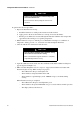
6. Internal damping filters out noise or the effects of rapid changes in the variable without
affecting measurement accuracy.
The damping value is the filter coefficient that approximates the time required for the output to
achieve 63% of its new value in response to a step change at the input. The actual time depends
on many factors, including sensor type and density of the process fluid. The meter rounds
down the chosen damping value to the nearest programmed filter coefficient. Programmed
filter coefficients, in seconds, are:
If desired, enter an internal damping value into the Damping text box in the Flow panel.
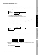
Table 7-2 Effect of flow direction on outputs and totalizers
Fluid flow
direction
Output or
totalizer
Flowmeter configuration
Forward Reverse
Fluid flowing
in same direction
as flow arrow
on sensor
Milliamp output Output increases as flow rate
increases
Output goes to 3.8 mA
Pulse output Output increases as flow rate
increases
Output remains at 0 Hz
Internal totalizers Flow totals increase Flow totals remain constant
Fluid flowing
in opposite direction
from flow arrow
on sensor
Milliamp output Output goes to 3.8 mA Output increases as flow rate
increases
Pulse output Output remains at 0 Hz Output increases as flow rate
increases
Internal totalizers Flow totals remain constant Flow totals increase
0.1 0.2 0.4 0.8 1.6 3.2 6.4 12.8