
Satellite Radio User Manual


26 Model IFT9701 Transmitter Instruction Manual
Power Supply and Output Wiring continued
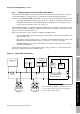
Figure 4-6 Wiring to pulse counter with internal pull-up resistor
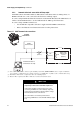
Figure 4-7 Wiring to pulse counter without internal pull-up resistor
Pulse counter
with pull-up to
internal power
Input
Ground (–) Frequency in (+)
IFT9701 pulse
output terminals
Pulse counter with
no pull-up
Pull-up
resistor
Input
Ground (–) Frequency in (+)
IFT9701 pulse
output terminals
External 5–30 VDC
power supply
To determine the value of the pull-up resistor,
see the graph earlier in this section.